Download a program for drawing electrical circuits. Review of the best programs for drawing electrical diagrams. Disadvantages of the free version
Drawing refers to the process of creating images of objects with accurate reproduction of their sizes using scale. Drawing electrical diagrams requires compliance with GOST symbols adopted to designate each element.
To create a document on a computer, you need software - a graphic editor that converts the PC user’s manipulations on the information input device into a drawing. The created document can be saved in in electronic format file and/or printed on paper in a specific format.
You can draw electrical circuits using any available graphic editor. However, special programs adapted for these purposes greatly facilitate routine work, allow you to use already prepared blanks of various elements from the library, quickly insert them into the right place, and conveniently edit them.
A novice user should be aware that drawing programs can be supplied and run:
1. free;
2. for money.
In the second option, functionality software significantly expanded. Moreover, over the past decade, among paid programs Among design engineers, entire CAD computer-aided design systems are popular. They not only automate the work, but also perform it very accurately. Due to this they have a high cost.
However, among CAD programs, programs that are supplied free of charge have begun to appear. Their functionality, of course, is a little limited, but it allows you to create high-quality electrical circuits at the initial and intermediate level of design.
KOMPAS-3D program
This well-known development of Russian programmers from the ASCON company allows you to draw diagrams in one plane or engage in 3D modeling. It is used by students, teachers and engineers in many countries. The program has a clear interface and a convenient set of tools for drawing.
For use by various specialists, the graphic editor is updated additional modules. The development kit for creating electrical circuits has a large library.
The program works in rectangular Cartesian coordinates, using linear dimensions in millimeters and angular dimensions in degrees. The reference material built into the program is well presented and allows you to independently understand all the issues that arise.
Compass 3D is distributed on a paid basis, but manufacturers provide anyone with the opportunity to evaluate the program for free for a month. For this purpose, you can download a demo version, which has minor limitations.
The program of the famous Autodesk company has been constantly improved for about 30 years, and is considered the most functional for performing complex design work. Built into the graphic editor, the help explains in detail the features of the algorithms. However, there is a lot of information, and it is difficult to master it on your own.
It is best to use the advice of an experienced mentor to master drawing in it. Even with its help, to fully master all the functionality, it will take more than one month of painstaking work, but to develop electrical circuits, you do not need to master the 3D format.
Feature of the program - use for calculations polar system coordinates and working with vectors. When plotting, for the convenience of the user, information is displayed in a rectangular Cartesian system. This allows you to determine the location of a point in two measurement systems.
In addition to using information from an extensive library, you can create frequently entered images of objects in the form of macros, assign hot keys to them, and use snapping to the object when displaying them on the monitor. This significantly speeds up the drawing process.
The program has numerous settings that require detailed study at the beginning, but later make the work much easier.
Quite often, detailed electrical circuits on paper take up large dimensions. AutoCAD allows you to create drawings on sheets different sizes. If previously a plotter was required for printing, now you can get by with an ordinary printer. The program implements the ability to divide a drawing into its component parts and print them on sheets of A4 paper with subsequent gluing along the borders.
Microsoft Visio program
The name of the product indicates that the paid graphic editor belongs to a company that occupies a leading position in software development. There are great opportunities for creating diagrams, diagrams and connecting them with data.
Users of Microsoft programs are familiar with this interface. For drawing electrical circuits, special templates on various topics have been created and placed in an accessible library.
A large number of tools are organized into groups and are conveniently configured for specific drawing conditions.
Microsoft Visio works in rectangular coordinates and is compatible with Word. Therefore, you can create in it graphic elements to insert into text documents. This is convenient to use when writing instructions for the purpose of visually explaining the material presented with diagrams and diagrams. Reverse insertion of texts and objects created in Word is also performed through a memory buffer.
Electrical circuits drawn in large sizes can also be printed not on a plotter, but on a printer in parts on sheets of A4 paper. As in AutoCAD, for this you need to set the printing settings.
Here, too, you can create frequently used element designations as templates for using them in further work. The program allows you to draw and draw relatively quickly.
To significantly simplify your work and speed up the creation of high-quality diagrams in Visio, you can use special additional stencil libraries designed for creating electrical diagrams electricity supply, modern electrical automation, electric drive and control devices. With the help of such component libraries, it is very easy to create professional circuits in accordance with standards.
Such kits for drawing electrical circuits will be useful, first of all, to electrical personnel involved in the design, installation, adjustment, repair and maintenance of electrical installations, as well as to anyone who needs to quickly and accurately draw an electrical circuit and design it in accordance with GOST.
CorelDRAW Technical Suite
Very powerful and expensive graphics program allows architects, designers and even fashion designers to perform a very wide range of work for the production of three-dimensional images. You can use it to create electrical circuits. But at the same time, its capabilities will be greatly reduced, which is not economically rational.
A9CAD 2.2.1
This is also a product of Autodesk. It largely repeats the work of the famous AutoCAD, but lacks the 3D design function. Distributed free of charge.
The CAD program's interface is tailored to the familiar appearance of Windows programs, and its size is 15.54 megabytes. This graphic editor supports files created in DWG formats and DXF, which are used as industry standards.
English language. The set of tools is quite extensive, modeled after AutoCAD. Image editing uses scaling, working with windows and layers, moving, inserting breaks, rotating, changing reflection, text overlay, color palette and other functions and styles.
With A9CAD 2.2.1 you can start drawing electrical circuits yourself.
There are many free graphic editors available on the Internet. Only Autodesk, in addition to A9CAD, offers several additional developments. To choose a program for drawing electrical circuits, you should evaluate your needs, capabilities and tasks.
Practical guide "How to draw a diagram in the A9CAD program" (pdf, 13 pages):
The times of using drawing boards are long gone; they were replaced by graphic editors, these are special programs for drawing electrical circuits. Among them there are both paid applications and free ones (we will consider the types of licenses below). We are sure that what we created short review will help you choose the most optimal software for the task from a variety of software products. Let's start with the free versions.
Free
Before moving on to the description of the programs, we will briefly talk about free licenses, the most common of which are the following:
- Freeware– the application is not limited in functionality and can be used for personal purposes without a commercial component.
- Open Source – product with “ open source", which allows you to make changes by adjusting the software to your own tasks. There may be restrictions on commercial use and paid distribution of the modifications made.
- GNU GPL– a license that practically does not impose any restrictions on the user.
- Public domain– almost identical to the previous version; copyright protection laws do not apply to this type of license.
- Ad-supported– the application is fully functional and contains advertisements for other products of the developer or other companies.
- Donationware– the product is distributed free of charge, but the developer offers to make donations on a voluntary basis for the further development of the project.
Having gained an understanding of free licenses, you can move on to software distributed under such conditions.
Microsoft Visio
This is an easy-to-use, but at the same time very convenient vector graphics editor with a rich functional set. Despite the fact that the main socialization of the program is the visualization of information from MS Office applications, it can be used to view and print radio circuits.
MS releases three paid versions that differ in functionality and a free version (Viewer), which is integrated into the IE browser and allows you to view files created in the editor. Unfortunately, to edit and create new diagrams you will need to purchase a full-featured product. Note that even in the paid versions, among the basic templates there is no set for full creation radio circuits, but it is not difficult to find and install.
Flaws free version:
- The functions of editing and creating diagrams are not available, which significantly reduces interest in this product.
- The program only works with the IE browser, which also creates a lot of inconvenience.
Compass-Electric
This software is an application to the CAD system of the Russian developer ASCON. For its operation, the installation of the KOMPAS-3D environment is required. Since this is a domestic product, it fully supports the GOST standards adopted by Russia, and, accordingly, there are no problems with localization.

The application is intended for designing any types of electrical equipment and creating sets of design documentation for them.
This is paid software, but the developer gives you 60 days to familiarize yourself with the system, during which time there are no restrictions on functionality. On the official website and on the Internet you can find a lot of video materials that allow you to familiarize yourself with the software product in detail.
In the reviews, many users note that the system has a lot of shortcomings that the developer is in no hurry to fix.
Eagle
This software is a comprehensive environment in which you can create both a schematic diagram and a printed circuit board layout for it. That is, place all the necessary elements on the board and perform tracing. At the same time, it can be performed both automatically and manual mode or by a combination of these two methods.

The basic set of elements does not contain models of domestic radio components, but their templates can be downloaded on the Internet. The application language is English, but localizers allow you to set the Russian language.
The application is paid, but it is free to use with the following functional limitations:
- The size of the mounting plate cannot exceed 10.0 x 8.0 cm.
- When routing, only two layers can be manipulated.
- The editor allows you to work with only one sheet.
Dip Trace
Is not separate application, but the whole software package, including:
- Multifunctional editor for developing circuit diagrams.
- Application for creating circuit boards.
- A 3D module that allows you to design housings for devices created in the system.
- A program for creating and editing components.

The free version of the software package, for non-commercial use, has minor restrictions:
- Circuit board no more than 4 layers.
- No more than one thousand pins from components.
The program does not provide Russian localization, but it, as well as a description of all functions software product can be found on the web. There are also no problems with the component database; initially there are about 100 thousand of them. On thematic forums you can find component databases created by users, including those for Russian GOST standards.
1-2-3 scheme
This is completely free application, which allows you to equip Hager electrical panels with equipment of the same name.

Functionality programs:
- Selecting a housing for an electrical panel that meets the standards for the degree of protection. The sample is taken from model range Hager.
- Complete with protective and switching modular equipment from the same manufacturer. Please note that the element base contains only models certified in Russia.
- Formation of design documentation (single-line diagram, specification that meets ESKD standards, drawing of appearance).
- Creating markers for electrical switchboard switching devices.
The program is completely localized for the Russian language, its only drawback is that the element base contains only the electrical equipment of the developer company.
Autocad Electrical
An application based on the well-known CAD system Autocad, created for designing electrical circuits and creating technical documentation for them in accordance with ESKD standards.

Initially, the database includes over two thousand components, while they are conditionally graphic symbols meet current Russian and European standards.
This application is paid, but you have the opportunity to get acquainted with the full functionality of the basic working version within 30 days.
Elf
This software is positioned as an automated workstation (AWS) for electrical designers. The application allows you to quickly and correctly develop almost any drawing for electrical projects linked to the floor plan.
The functionality of the application includes:
- Arrangement of UGO when designing electrical networks laid openly, in pipes or special structures.
- Automatic (from the plan) or rune calculation of the power circuit.
- Drawing up specifications in accordance with current regulations.
- Possibility of expanding the element base (UGO).

The free demo version does not allow you to create or edit projects; you can only view or print them.
Kicad
This is a completely free open source software package. This software is positioned as an end-to-end design system. That is, you can develop a circuit diagram, use it to create a circuit board and prepare the documentation necessary for production.

Characteristics systems:
- The use of external tracers is allowed for board layout.
- The program has a built-in printed circuit board calculator; elements can be placed on it automatically or manually.
- Upon completion of the tracing, the system generates several technology files (for example, for a photoplotter, drilling machine, etc.). If desired, you can add a company logo to the PCB.
- The system can create layer-by-layer printouts in several popular formats, as well as generate a list of components used in development for order generation.
- It is possible to export drawings and other documents to pdf formats and dxf.
Note that many users note that the system interface is poorly thought out, as well as the fact that in order to master the software, you need to thoroughly study the documentation for the program.
TinyCAD
Another free and open source application that allows you to create circuit diagram drawings and has the functions of a simple vector graphics editor. The basic set contains forty different component libraries.
 TinyCAD - a simple editor for circuit diagrams
 The program does not provide PCB tracing, but it is possible to export the netlist to third party application. Export is carried out with support for common extensions.
The application only supports English language, but thanks to the intuitive menu there will be no problems with mastering it.
Fritzing
Free project development environment based on Arduino. It is possible to create printed circuit boards (the layout must be done manually, since the auto-routing function is frankly weak).

It should be noted that the application is “tailored” for quick creation sketches to explain the operating principle of the designed device. For serious work, the application has too small a base of elements and a very simplified diagram.
123D Circuits
This is a web application for developing Arduino projects, with the ability to program the device, simulate and analyze its operation. A typical set of elements contains only basic radio components and Arduino modules. If necessary, the user can create new components and add them to the database. It is noteworthy that the developed printed circuit board can be ordered directly from the online service.

In the free version of the service, you cannot create your own projects, but you can view other people’s developments that are in the public domain. For full access to all features, you must subscribe ($12 or $24 per month).
Note that due to poor functionality virtual environment development is of interest only to beginners. Many of those who used the service drew attention to the fact that the simulation results differed from real indicators.
XCircuit
Free multi-platform application (GNU GPL license) for quickly creating circuit diagrams. The functional set is minimal.

The application language is English, the program does not accept Russian characters. You should also pay attention to the atypical menu, which you need to get used to. In addition, contextual hints are displayed on the status bar. The basic set of elements includes UGO of only the main radio components (the user can create his own elements and add them).
CADSTAR Express
This is a demo version of the CAD software of the same name. Functional limitations affected only the number of elements used in the development circuit (up to 50 pieces) and the number of contacts (no more than 300), which is quite sufficient for small amateur radio projects.

The program consists of a central module, which includes several applications that allow you to develop a circuit, create a board for it and prepare a package of technical documentation.
The basic set includes more than 20 thousand components; additional libraries can be downloaded from the developer’s website.
A significant drawback of the system is the lack of support for the Russian language; accordingly, all technical documentation is also presented online in English.
QElectroTech
A simple, convenient and free (FreeWare) application for developing electrical and electronic circuits- drawings. The program is a regular editor; no special functions are implemented in it.

The application language is English, but there is a Russian localization for it.
Paid applications
Unlike software distributed under free licenses, commercial programs, as a rule, have much more functionality and are supported by developers. As an example, we will give several such applications.
sPlan
A simple editor program for drawing electrical circuits. The application comes with several component libraries that the user can expand as needed. You can work with several projects simultaneously by opening them in separate tabs.

Drawings made by the program are stored as vector graphics files in its own format with the “spl” extension. Conversion to standard ones is allowed raster formats Images. It is possible to print large diagrams on a regular A4 printer.
The application is not officially released in Russian localization, but there are programs that allow you to Russify the menu and contextual hints.
In addition to the paid version, there are two free implementations: Demo and Viewer. In the first one there is no way to save and print the drawn diagram. The second provides only the function of viewing and printing files in the “spl” format.
Eplan Electric
Multi-module scalable CAD system for developing electrical projects of varying complexity and automating the process of preparing design documentation. This software package is now positioned as a corporate solution, so it will not be of interest to ordinary users, especially if you take into account the cost of the software.

Target 3001
A powerful CAD complex that allows you to develop electrical circuits, trace printed circuit boards, and simulate operation electronic devices. The online library of components contains more than 36 thousand different elements. This CAD is widely used in Europe for PCB routing.

The default language is English, it is possible to set the menu in German or French, there is no official Russian localization. Accordingly, all documentation is presented only in English, French or German.
The cost of the simplest basic version about 70 euros. For this money, tracing of two layers with 400 pins will be available. The cost of the unlimited version is around 3.6 thousand euros.
Micro-Cap
An application for modeling digital, analog and mixed circuits, as well as analyzing their operation. The user can create in the editor electrical circuit and set parameters for analysis. After this, with one click of the mouse, the system will automatically perform the necessary calculations and display the results for study.

The program allows you to establish the dependence of the parameters (ratings) of elements on temperature conditions, illumination, frequency characteristics etc. If the circuit contains animated elements, for example, LED indicators, then their state will be displayed correctly, depending on the incoming signals. When modeling, it is possible to “connect” virtual measuring instruments, as well as monitor the status of various components of the device.
The cost of the full-featured version is about $4.5 thousand. There is no official Russian localization of the application.
TurboCAD
This CAD platform includes many tools for designing various electrical devices. A set of special functions allows you to solve engineering and design problems of any level of complexity.

Distinctive features– fine-tuning of the interface for the user. Lots of reference books, including in Russian. Despite the lack of official support for the Russian language, there are Russifiers for the platform.
For ordinary users, purchasing a paid version of the program in order to develop electrical circuits for amateur devices will be unprofitable.
Designer Schematic
An application for creating electrical circuits using radioelements produced by Digi-Key. The main feature of this system is that the editor can use mechanical design to build circuits.

Component databases can be checked for compliance at any time and, if necessary, updated directly from the manufacturer’s website.
The system does not have its own tracer, but the netlist can be loaded into a third-party program.
It is possible to import files from popular CAD systems.
The approximate cost of the application is about $300.
A program for designing electrical wiring in a house is a necessary tool for organizing and arranging an optimized power supply for a home, be it a private house or your own apartment. Today in computer network You can find a considerable number of programs for designing electrical wiring diagrams in apartments or houses.
Benefits of Programming
Programming various electrical wiring diagrams saves the consumer from “fussing” with homemade calculations of electrical wiring diagrams in his own home. The program, which is purchased or downloaded for free from the Internet, provides an accurate calculation of the electrification of a house or apartment.
The time that will be spent on dubious calculations of the required cross-section and the need for the volume of cable and wire products to ensure a full calculation of the wiring in the premises can be reduced by turning to programming the design of electrical wiring in your own home.
Those who want to arrange electrical wiring in their own home with their own hands have a desire to independently calculate the volume of needs for cable products. Independent calculations are fraught with unexpected troubles, such as destruction of the surface of the wall covering, ignition of wires and the occurrence of a fire.
To avoid such negative forecasts, you need not to be lazy and turn to a software product that will give correct solution related to the full range of these issues.
There is no need to worry about the difficulties of handling the program in this area. The developers of programs for designing electrical wiring in private homes took into account all the wishes of consumers.
Important! The programs are adapted for a wide range of consumers. A computer product can be used by those segments of the population that have access to technical equipment with an Internet connection. Otherwise, you can give advice on purchasing software on hard media.
What the program can do
The capabilities of computer programs cover a large volume of drawing up plans for creating electrical wiring diagrams with all its characteristics. With these programs you can do the following:
- calculate the power supply diagram;
- calculate the total voltage loss;
- determine the required volume of demand for cable products with the required cross-section;
- draw up a specification of basic and auxiliary materials for wiring installation;
- draw a layout of the lighting of the premises, indicating the placement points of lighting fixtures with lamps of the required power.

Note! The accuracy of determining the wiring cross-section depends on the accuracy of the input data entered. An error can lead to overheating and melting of the electrical wiring.
Types of programs
In their work, electricians often have to perform many calculations related to various indicators of electrical wiring in the house. After this, you have to spend a lot of time drawing electrical diagrams and selecting the appropriate equipment and instruments.
To speed up the process of creating plans for organizing electrical work, many versions of the software product have been developed, as well as programs for drawing floor plans with electrical wiring. For those interested in this issue, below is a description of the most popular electrical wiring programs.
Electrician program
This service has multifunctional capabilities:
- Performs power calculations of three-phase and single-phase electricity consumers;
- Determines the amount of current and the amount of power based on the cross-sectional area of the electrical wiring;
- Calculates peak values of short circuit currents;
- Determines voltage losses throughout the entire electrical circuit;
- Establishes the required cross-section of cable products according to the electrical wiring plan in a specific apartment;
- Calculates the ground loop;
- Using the program, check the correct choice of cross-section for a specific electrical wiring.
The program has such a clear and simple interface that not only a specialist, but also a “home-grown” master can use it.

The multifunctional operating system of the Electric program has extensive capabilities in the field of designing the electrification of private housing construction.
Before you begin electrical wiring installation work, you need to create a drawn diagram or detailed drawing with a plan for installing wire products. This is easy to do with the Electrician program. The system requests information about the area of the apartment, house, as well as the number and location of electricity consumers with the installation of sockets. The initial data is entered into the interface windows.
The standards regulate the installation of 1 socket per 6 sq.m. of usable housing area. At the same time, the requirements for the number of electrical connection points in the kitchen (at least 3 sockets) are taken into account, and one socket is allowed to be installed in the bathroom.
All information is entered into the program interface. As a result of instant analysis, the installation of electrical wiring in a given area is displayed on the monitor.
Electrical circuit design
Creating a wiring diagram for a building begins with drawing a plan for the location of cables and wires in the premises of the house. The electrification drawing contains the following:
- The size of the area of the apartment or house;
- Placement of sockets and other points of connection of electrical appliances and equipment to the electrical network;
- The amount of energy consumed in peak situations (the value is the main indicator for calculating the cross-section of cables and wires);
- Safe connection to the network of electricity consumers.
With the help of "Electrician" you can easily draw and think through the specific design of the electrical network in your home.

The free program "Electric 6.7" is a modified software system "Electric". "Electrician 6.7" allows:
- make a power calculation for 1 and 3 phase current;
- calculate the required cross-section of electrical wiring;
- find out the peak current value during a short circuit;
- create a specification for the needs of cable and wire products for the electrification of a home or other housing;
- calculate the device of a single or grounding loop.
Additionally, using the software product, you can check the wire cross-section for:
- maximum heating of conductors;
- the amount of voltage loss;
- economic feasibility of current density;
- current strength at which metal melting in wires can occur.
Additional Information. Along with this program, specialists have developed a series of software. Computer programs take into account the nuances of the state of the building at the time of planning the electrical wiring.
Examples of software for designing electrical wiring in a house
Mobile Electrician program
- The service, in addition to the capabilities of the program described above, is equipped with a number of additional functions. The operating system interface is not much different from “Electric”;
- Mobile Electrician software can be found on the Internet on many sites. As a rule, they offer to download free versions of the program.
"Compass-electric"
- The operating system was created for the design of electrical equipment and electrical circuits industrial use. The diagram editor can draw the basic composition of the network with detailed specifications or a list of elements used;
- The program has more than 6 thousand standard products and several hundred graphic images, conventional signs. It is not used for designing electrical wiring in residential premises;
- The software consists of two modules: one acts as a diagram editor, the second part contains information base. A simple and accessible interface will help any beginner in designing power wiring in their own home;
- Electrical compass is designed for designing electrical systems in large houses, mansions and villas. Complex facilities of such buildings are saturated with both low-voltage and high-voltage equipment;
- "Compass-Electric" will calculate the arrangement of a home ownership with an automated control room for managing the energy system and relay protection.

sPlan
- The sPlan program is distributed on a paid basis. Despite this circumstance, the operating system is very popular. The authors of the program sought to create a product so that it could be used by people who do not have deep knowledge in the field of electrical engineering;
- In order to correctly build a drawing, just drag the necessary element into the diagram construction field. The construction of an electrical drawing occurs with a simple mouse movement. If the drawing occupies an area larger than A 1 format, then it is divided into fragments of A 4 format. This allows you to print the diagram on a standard printer.
Those who are interested in how to optimally arrange the electrification of their home are recommended to use the “Electrician” program. The program interface contains many functional options that will be useful to specialist electricians and will become a good assistant in planning electrical wiring directly for the owners of a house or apartment.
Video
Today I want to talk about a very convenient project development environment for Arduino — .
Fritzing is an excellent open source developer tool for learning, prototyping and sharing projects based on Arduino. He works for Windows, Mac OS And Linux.
Allows you to develop a schematic diagram of a device, and create its representation in the form of connecting layouts of elements that look very professional. It also makes it possible to design a printed circuit board for its further manufacture. Unlike other design systems, A simple interface that makes electronic circuit design intuitive.

This is what the wiring diagram looks like
Download and install Fritzing
To install, go to the download page and choose yours operating system. To install on your computer, follow the instructions on the page. There are no special features in the installation, so I will not dwell on this in more detail. “out of the box” already comes with a large number of libraries of various elements. There are both basic components such as wires, buttons, resistors, and various specialized components such as circuit boards Arduino and sensors. If you need to add a new library, or your own component to the library, no problem. I will tell you how to do this in a separate article.
Let's start working at Fritzing
When you first open a project in , the following window will appear in front of you

Fritzing welcome window
Switching to the Development Board tab we will see the following screen

Breadboard Tab
On the right side of the screen there is a toolbar with all the elements and options. If a component is being customized, the configurable options for that component are displayed at the bottom of the toolbar.
Components menu
Let's place a component of some kind at the bottom of the breadboard. We will design simple diagram, which simply powers the LED. For our circuit we need one resistor. Select and drag the resistor onto the work area as shown below.

Selecting an element
Drag the resistor onto the breadboard so that each pin ends up on a separate column on the board. When a component connects to a particular column, the entire column turns light green as shown below. The green line indicates the electrical connection between the holes.

The vertical columns of the breadboard are connected to each other
Configuring component parameters
For a selected element, we can configure its parameters at the bottom of the toolbar to change its resistance value, tolerance and pin spacing. Note that the distance between the pins is specified in mils. 1 mil is 1/1000 of an inch.
Rotate → Rotate 90° clockwise

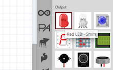
Selecting an LED
We place the LED on the board next to the resistor, as shown below. As long as the resistor and LED are not connected to a power source or to each other. Note that the green lines are not touching.

Placing the LED
Just like on a real breadboard, we can add wires to connect the elements we need. Hover your mouse over the hole on the breadboard and notice that it turns blue. This means you can start running the wire. Click the hole on the breadboard and, without releasing the left mouse button, drag the other end of the wire to the desired point. I connected the positive lead of the LED to the top row of pins on the breadboard and connected the second lead of the LED to a resistor.

Connecting wires
To complete our project, we'll add a power source. Select and drag the power battery from the toolbar onto the breadboard.

Choosing a battery
Arrange the power wires as shown below - the positive battery lead on the top line and the negative lead on the bottom line with the contacts. The pin spacing on the battery output does not match the spacing between the top power rails of the breadboard. Therefore, we will connect the positive terminal of the battery with the upper power bus, and move the negative terminal to a level corresponding to the lower power bus. The connection of the power battery to our circuit should end up looking like the figure below.

Adding a battery
That's all. Our simple circuit, which includes a 3V battery, an LED, and a current-limiting resistor, looks pretty decent. And all this by simply dragging elements and connecting the required pins! To use it anywhere, it remains to save it in the format we require. To do this, go to the program menu,
File → Export → asImage and select the desired format.
That's all I have for today, save the file - we will need it later. In the next publication dedicated to Fritzing, I will tell you how to create a circuit diagram of a device based on our project on a breadboard.
We are increasingly using computers and virtual instruments. Now you don’t always want to draw diagrams on paper - it takes a long time, it’s not always beautiful and it’s difficult to correct. In addition, a program for drawing circuits can produce a list of necessary elements, simulate a printed circuit board, and some can even calculate the results of its operation.
Free programs for creating diagrams
There are a lot of good ones on the web free programs for drawing electrical circuits. Their functionality may not be enough for professionals, but to create a power supply diagram for a house or apartment, their functions and operations will be enough. Not all of them are equally convenient, some are difficult to learn, but you can find several free programs for drawing electrical circuits that anyone can use, their interface is so simple and intuitive.
The easiest option is to use the standard Windows program Paint, which is available on almost any computer. But in this case, you will have to draw all the elements yourself. Special program for drawing diagrams allows you to insert ready-made elements into the right places, and then connect them using communication lines. We'll talk about these programs further.
A free program for drawing diagrams does not mean bad. This photo shows work with Fritzing
The program for drawing QElectroTech circuits is in Russian, and it is completely Russified - menus, explanations - in Russian. Convenient and intuitive interface - a hierarchical menu with possible elements and operations on the left side of the screen and several tabs at the top. There are also quick access buttons for performing standard operations - saving, printing, etc.

There is an extensive list of ready-made elements, it is possible to draw geometric shapes, insert text, make changes in a certain area, change the direction in a particular fragment, add rows and columns. In general, the program is quite convenient, with the help of which it is easy to draw a power supply diagram, enter the names of the elements and ratings. The result can be saved in several formats: JPG, PNG, BMP, SVG; data can be imported (opened in this program) in QET and XML formats; exported in QET format.
The disadvantage of this program for drawing diagrams is the lack of videos in Russian on how to use it, but there are a considerable number of lessons in other languages.
Graphics editor from Microsoft - Visio
For those who have at least a little experience working with Microsoft products, master working in graphic editor Visio will be easy. U of this product There is also a fully Russified version, with good level translation.

This product allows you to draw a diagram to scale, which is convenient for calculating the number of wires needed. Large library of stencils with symbols, the various components of the circuit, makes the work similar to assembling a construction set: you need to find the right element and put it in place. So how to work in programs of this type Many people are used to it; searching is not difficult.
The positive aspects include the presence of a decent number of lessons on working with this program for drawing diagrams, and in Russian.
Compass Electric
Another program for drawing diagrams on a computer is Compass Electric. This is a more serious product that is used by professionals. There is a wide functionality that allows you to draw various plans, flowcharts, and other similar drawings. When transferring the circuit into the program, a specification and wiring diagram are generated in parallel and they are printed.
To get started, you need to load the library with system elements. When you select a schematic image of a particular element, a window will “pop up” in which there will be a list of suitable parts taken from the library. A suitable element is selected from this list, after which its schematic image appears in the specified place in the diagram. At the same time, a designation corresponding to GOST with continuous numbering is automatically entered (the program changes the numbers itself). At the same time, the parameters (name, number, denomination) of the selected element appear in the specification.

In general, the program is interesting and useful for developing device circuits. It can be used to create a wiring diagram in a house or apartment, but in this case its functionality will be almost not used. And one more positive point: there are many video lessons on working with Compass-Electric, so it will not be difficult to master it.
DipTrace program - for drawing single-line diagrams and circuit diagrams
This program is useful not only for drawing power supply diagrams - everything is simple here, since you only need a diagram. It is more useful for PCB development because it has a built-in function for converting an existing schematic into a PCB trace.
To get started, as in many other cases, you must first load the libraries with the element base available on your computer. To do this, you need to launch the Schematic DT application, after which you can load the libraries. They can be downloaded from the same resource where you will get the program.
After downloading the library, you can start drawing the diagram. First, you can “drag” the necessary elements from the libraries onto the workspace, expand them (if necessary), arrange them and connect them with connection lines. After the circuit is ready, if necessary, select the line “convert to board” in the menu and wait for a while. The output will be a finished printed circuit board with the arrangement of elements and tracks. You can also watch it in 3D appearance finished board.
Free ProfiCAD program for drawing electrical circuits
Free program for drawing diagrams ProfiCAD is one of best options for the home handyman. It is easy to use and does not require special libraries on your computer - it already contains about 700 elements. If there are not enough of them, you can easily replenish the database. The required element can simply be “dragged” onto the field, rotated there in the desired direction, and installed.

Having drawn the diagram, you can get a table of connections, a bill of materials, a list of wires. Results can be obtained in one of the four most common formats: PNG, EMF, BMP, DXF. A nice feature of this program is that it has low hardware requirements. It works fine on systems from Windows 2000 and higher.
This product has only one drawback - there is no video about working with it in Russian yet. But the interface is so clear that you can figure it out yourself, or watch one of the “imported” videos to understand the mechanics of work.
If you'll be working with a diagramming program frequently, it's worth considering some of the paid versions. How are they better? They have wider functionality, sometimes more extensive libraries and a more thoughtful interface.
Simple and convenient sPlan
If you don't really want to deal with the intricacies of working with multi-level programs, take a closer look at the sPlan product. It has a very simple and understandable structure, so after an hour and a half of work you will already be able to navigate freely.
As usual in such programs, a library of elements is required; after the first launch, they must be loaded before starting work. In the future, if you do not move the library to another location, no configuration is needed - the old path to it is used by default.

If you need an element that is not in the list, you can draw it, then add it to the library. It is also possible to insert extraneous images and save them, if necessary, in the library.
Among other useful and required functions— auto-numbering, the ability to change the scale of an element by rotating the mouse wheel or ruler for more understandable scaling. In general, a pleasant and useful thing.
Micro-Cap
This program, in addition to constructing a circuit of any type (analog, digital or mixed), also allows you to analyze its operation. Are set initial parameters and get the output. That is, it is possible to simulate the operation of the circuit under various conditions. A very useful opportunity, which is probably why teachers and students really like it.
The Micro-Cap program has built-in libraries that can be expanded using a special function. When drawing an electrical circuit, the product in automatic mode develops circuit equations and also carries out calculations depending on the specified values. When the nominal value changes, the output parameters change immediately.

A program for drawing power supply diagrams and more - more for simulating their operation
The values of the elements can be constant or variable, depending on various factors - temperature, time, frequency, state of some circuit elements, etc. All these options are calculated, and the results are presented in a convenient form. If there are parts in the circuit that change their appearance or state - LEDs, relays - when simulating operation, they change their parameters and appearance thanks to animation.
The program for drawing and analyzing Micro-Cap circuits is paid, in the original it is in English, but there is also a Russian version. Its cost in the professional version is more than a thousand dollars. The good news is that there is also a free version, as usual with reduced capabilities (smaller library, no more than 50 elements per circuit, reduced speed). This option is also quite suitable for home use. It’s also nice that it works fine with any Windows system from Vista and 7 and above.