Homemade anti-theft device on Arduino Uno and fingerprint sensor. Homemade anti-theft device on Arduino Uno and fingerprint sensor Codes – Enroll Example
To create such a project, the author had to modify the launch system of his vehicle. The main connection is the IG conductor from the ignition switch, through which power is supplied to the voltage regulator, and then to the Arduino itself to turn it on, as well as turn on the finger scan sensor. If the finger scan is successful, the system activates the relay box and it controls the starter relay. Now you can start the car. The sensor works for 10 seconds, and it can be restarted by repeating the ignition start cycle. If, in the allotted time, the sensor did not detect a fingerprint or it does not match the specified one, then the starting system will be disabled and the engine will not start.
Since each car has its own start configuration system, it is necessary to look into the electrical circuit before modifying the engine start system.
This article describes how to connect an anti-theft device to a Mitsubishi Lancer 2000 2-door coupe.
Materials:
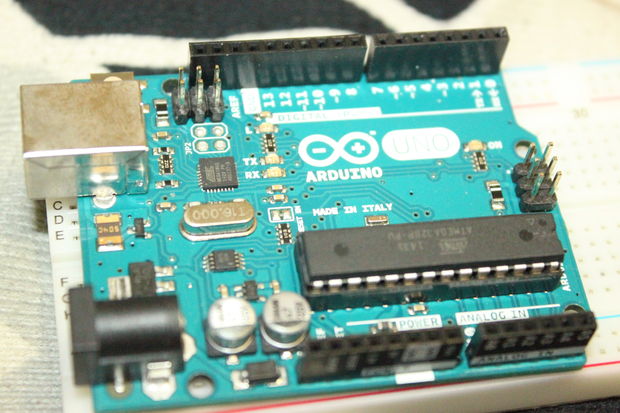
- Arduino Uno.
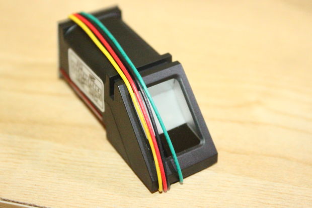
- Fingerprint sensor.
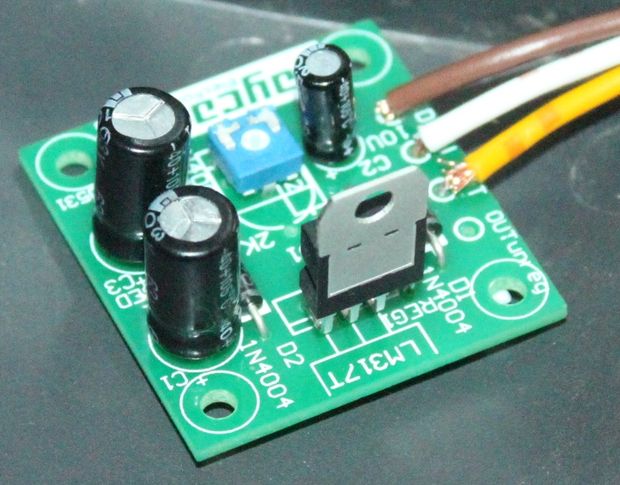
- Source of power.
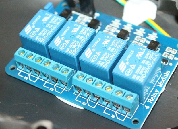
- Relay block.
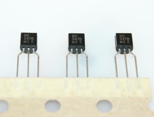
- NPN transistor BC547B
- Resistor 1 kOhm


Wiring diagram:
The circuit is slightly modified in accordance with the components used. Please note that this is only valid for this vehicle model.

Step 1 Preparing software components:
The Arduino IDE downloads and adds the .
The file from the blank.ino library is loaded into the Arduino, which will serve as an interface between the sensor and the microcontroller.
The program is installed, and the sensor is connected to the Arduino as shown in the diagram. Then the fingerprint is loaded through the installed program.

The sensor is now connected as shown in the following diagram. After that, the author proceeds to download the main program. An LED with a resistor is connected to pin 12.
The program will work primarily on the Adafruit Fingerprint tutorial. Only a 10-second sensor off timer has been added to the program code. You can download the code below the article.

Step 3 assembly:
Part 1:
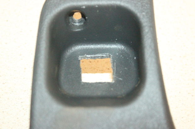
To begin with, the screws under the dashboard are unscrewed. The lower part of the panel is removed, and the sensor can be placed in the free space.


Part 2:
In the selected location for the sensor, a zone is cut out for its reliable installation.


part 3:
The Arduino board is installed behind the fingerprint sensor. The place to install the Arduino was slightly undermined so that the board could take the correct position.


part 4:
The regulated power supply is installed behind the dashboard on the driver's side.

part 5:
The remaining components of the equipment are connected according to the diagram at the beginning of the article.


Step 4 installation:
The necessary wires are connected and the device is installed under the dashboard. The author makes sure that there is no short circuit.
To create a simple biometric security system to protect your car from unauthorized access, we need a fingerprint sensor and an Arduino microcontroller. This project uses the Adafruit tutorial. For ease of repetition, the complete code from this material is used, with minor modifications.
First, we modify the launch system of the vehicle. The main connection is the IG wire from the ignition switch, which supplies power to the voltage regulator, then to the Arduino microcontroller to turn it on and off and scan the finger on the sensor for 10 seconds. When the fingerprint matches, the system activates a relay box that controls the starter relay. Now you can start the engine. After 10 seconds, the fingerprint sensor turns off. You can turn it on again by repeating the ignition start cycle. If within 10 seconds the sensor does not detect a fingerprint or the fingerprint does not match the reference, then the start system is disabled and the engine does not start.
Since each vehicle has its own start configuration system, you should consult with a vehicle electrician or review the wiring diagram before modifying the start system.
Please note that the fingerprint sensor does not start the engine. It only activates and deactivates the starter relay, which prohibits or allows the engine to start.
In this project, the anti-theft device is installed on a 2-door Mitsubishi Lancer 2000 coupe.
Step 1: Components Used
Step 4: Downloading the main program
Connect the fingerprint sensor as shown in the diagram and download the main program. Connect an LED and a resistor to pin 12 to check if the operation is correct.
The program works on the principle of the Adafruit Fingerprint training material. However, I changed the programming code a little and added a timer to turn off the sensor after 10 seconds to avoid distraction from the blinking sensor LED.
Step 5: Assembly Part 1
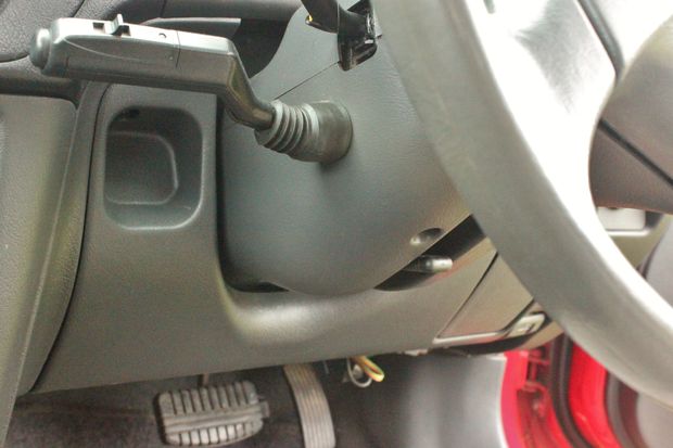
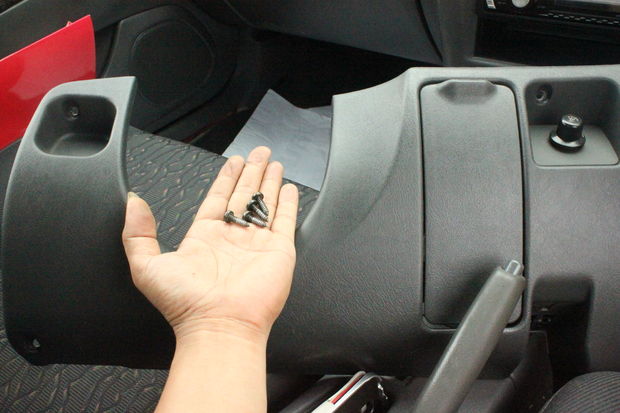
Remove the screws under the dashboard. Loosen the hood latch release lever. Remove the lower part of the dashboard. Place the sensor in a free space.
Step 6: Assembly Part 2

Measure the required distance and cut out a small area to securely install the sensor.
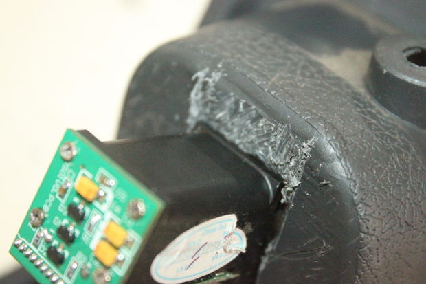
Step 7: Assembly Part 3
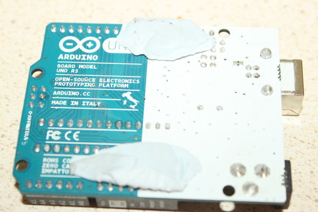
The Arduino Uno is best placed behind the fingerprint sensor. I trimmed the footprint a bit to get the Arduino Uno board in the correct position.
If you are using a relatively old device, then do not get upset ahead of time. Instead of exchanging an old laptop for a more modern one with a biometric sensor already built in, you can connect USB to it.
The PQI Mini USB Fingerprint Reader is a great choice for those who want to give their old hardware a second life. The scanner has been specifically designed to work with the new Hello feature available on Windows 10 devices. However, the device also supports Windows 7 and 8 operating systems.
One of the main advantages of the sensor is that it has the ability to 360-degree scanning. So you don't have to worry about the best way to connect your device to your PC. Use the nearest USB port and get started. When the scanner needs a fingerprint, it will automatically turn to the right place and compare the received data with the saved copy.
PQI Mini USB Fingerprint Reader can store up to 10 different profiles in memory. Therefore, the device is great for sharing or when you need to scan an additional finger (if the “primary” one gets dirty or injured).
The PQI Mini USB Fingerprint Reader is available at a very affordable price, making it a great choice for those looking for a starter model. In addition, the scanner is portable enough to carry around without too much trouble.
Verifi P2000 Fingerprint Reader

If you are using a desktop computer on which it is not so easy to get to USB ports, then pay attention to the Verifi P2000 Fingerprint Reader. It easily connects to a PC, and most importantly, it can be placed near the computer for more comfortable use.
The scanner is made of impact-resistant metal and will last more than one year. Despite the solid construction, it has a good fingerprint recognition rate. So you don't have to keep changing your finger position just to get a perfect match. In most cases, it will be enough to swipe the sensor just once.
When creating the P2000, Verifit planned to make the device strong and durable so that it does not have any effect on the scanning process and the accuracy of recognition results. The Verifi P2000 Fingerprint Reader is portable enough to be easily carried around. In addition, it is compatible with a much larger number of computers than other similar models.
Kensington VeriMark

For an incredibly small fingerprint scanner, the Kensington VeriMark has just about everything you need to work comfortably. The model boasts support for 360-degree scanning and a small size. But the main thing that makes Kensington VeriMark so valuable is the additional functionality.
All received data is stored in encrypted form. When the sensor scans a fingerprint, it immediately encrypts it. It is impossible to interrupt this process, so it will not be possible to hack the software or hardware and extract biometric data.
In addition, the device uses a special template for decoding received scans, which only the manufacturer has. This makes it more secure from hacker attacks and other attempts to gain unauthorized access.
The scanner supports relatively old ports regardless of the release version. If you are using a model with, then using a USB-C to USB-A adapter, the device can be connected to a relatively old laptop or computer without support for more modern USB ports.
Benss Fingerprint Reader Analyzer

Benss Fingerprint Reader Analyzer is another scanner that can make your life easier and save you a lot of trouble. As a rule, simpler models first take one control shot, after which all subsequent prints are compared with the original result. This means that if something happens to the original image (with which all other scans are compared), then the probability of matching the final results will drop significantly.
Benss Fingerprint Reader Analyzer is powered by a self-learning algorithm that automatically creates and updates your profile with every touch. The longer you use the device, the more accurate the results will be. This makes it harder to fool the scanner with fake fingerprints. Since the sensor constantly scans your finger and updates the database, it immediately detects attempts to gain unauthorized access.
This is one of the most effective devices for countering hacker attacks. Its False Acceptance Rate is less than 0.002%, which means that you will have to really try to hack the device. At the same time, it does not greatly complicate the work, its FRR (False Rejection Rate - denial of access to a person registered in the system) is only 3%.
IDEM BioScan Compact

If you're looking for a scanner with customization options, IDEM BioScan Compact is the one for you. To expand its basic capabilities and get additional functionality, it is enough to download special software from the official website of the manufacturer.
After that, you can encrypt individual files and folders on your computer, as well as store login and password data for accessing websites in a special program. So you can log in to any Internet portals with the usual touch of your finger on the sensor.
Even if you do not take into account the additional functionality, the BioScan Compact is considered a worthy model. The device is capable of storing up to 10 different fingerprints, boasts small dimensions, as well as built-in protection for recognizing fake biometric data.
Blucoil SecuGen Hamster Pro 20

The Blucoil SecuGen Hamster Pro 20 is the ideal fingerprint scanner for professional needs. Due to the fact that the model offers advanced security settings, its cost is almost twice as high as other devices on our list.
In addition, it is one of the few scanners with official Linux support. Therefore, no matter which operating system you use, the sensor is suitable for any task.
The SecuGen Hamster Pro 20 is rugged and scratch, water and dust resistant. The scanner is able to track traces left over from previous scans and reject fuzzy results.
In addition, the Blucoil SecuGen Hamster Pro 20 is an energy-saving device, so it automatically turns off if no one uses it for a long time.
Additional security
In recent years, a huge number of mobile and desktop devices with built-in fingerprint scanners have been released, and every year their number is only growing. If your computer does not have a built-in sensor for recognizing biometric data, then you should not be upset. There is a huge variety of USB scanners for PCs and laptops that are compatible with almost all popular models.
Since I don't have a car, I don't have to carry my keys with me everywhere. Because of this, it turned out that I found myself without keys several times outside the house and I had to wait until one of the relatives returned home and let me in, and at some point I decided that I needed to do something about it and designed a homemade garage lock.

In this project, I will show you how to make a fingerprint lock on the front door.
Step 1: Materials


Here is a list of required materials and tools.
Electronics:
- Fingerprint scanner (and JST connector)
- LCD kit (with ATmega328)
- ATtiny85
- NPN transistor
- Speaker-tweeter
- speaker wire
- Case (in step 9 there will be files for 3D printing)
- Copper film
- Voltage regulator 5V
- Battery 9V
- Battery connector 9V
- SPDT switch
For convenience, I will attach a ready-made wishlist on the Sparkfun website.
Tool:
- Soldering iron and solder
- Insulating tape
- Wires and jumpers
- Nippers / stripper
- prototyping board
- Various resistors
- screws
- Drill
- Several LEDs for testing
- FTDI 5V board
- hot glue gun
- Access to a 3D printer
- Optional: IC socket (8-pin for ATtiny and 28-pin for ATmega)
- Optional: another Arduino board / 10uF capacitor (details in step 5)
Step 2: Device Schematic


The LCD kit purchased from Sparkfun came with an ATmega328 driving the display. The ATmega328 is quite powerful and can be used not only for display control, but also for other tasks. In view of this, we can use it instead of Arduino to communicate with the fingerprint scanner and send commands to the ATtiny85, control the display and the buzzer.
To prevent the biometric door lock from working all the time, I built a switch into it that works the moment the case closes. If the case is closed, the device is not powered, and we save battery resources.
Important note: The fingerprint scanner works at 3.3V, so I recommend using a voltage divider that will convert the signals from the ATmega to 3.2V. The voltage divider consists of a 560 ohm resistor between D10 / scanner pin 2 and a 1 kΩ resistor between GND / scanner pin 2.
LCD Pinout:
- D10 - pin 1 of the scanner (black wire)
- D11 - pin 2 of the scanner (via voltage divider)
- D12-ATtiny85
- D13 - Squeaker
ATtiny85 pinout:
- Pin 5 (0 in the program code) - input from ATmega
- Pin 3 (4 in the program code) - transistor / yellow LED
- Pin 7 (2 in the program code) - indication LED
Step 3: Assembling the Components from the LCD Kit

The name of the step speaks for itself: handy-dandy quick start/assembly guide
Step 4: Assembling the Circuit on the Prototyping Board


The placement of the components on the board is up to you, just try to solder the wires so that they look in one direction and do not break.
After assembly, I covered the top and bottom of the board with hot glue - this secured and insulated the circuit elements. Hot glue will not damage the chip.
As with the main board, solder everything to the ATtiny board and apply hot glue to secure and isolate the components. The voltage regulator can get very hot, so it's a good idea not to apply hot glue to it or surfaces near it. It's also best not to hot glue the ATtiny board, as you may want to remove and reprogram it.
Step 5: Programming the ATmega328

As mentioned in step 2, the ATmega328 has a strong enough processor and enough pins to drive the LCD while it drives other additional components. To achieve this, you need to program the chip.
If you have an Arduino Uno or Duemilanove, you can simply remove the chip from them and replace it with the one that came with the kit. Alternatively, you can find an FTDI Basic Breakout (5V) board and solder headers to its side (see pictures in step 3)
You will also need to fill in the code in the "Duemilanove w/ ATmega328" mode.
The code below is a working program for checking the device's performance.
#include "LiquidCrystal.h" LiquidCrystal lcd(2,3,4,5,6,7,8); void setup() ( pinMode(9, OUTPUT); // backlight pinMode(13, OUTPUT); // tweeter lcd.begin(16, 2); // 16 characters wide, 2 characters high digitalWrite(9, HIGH) ; //turn on the backlight lcd.print(" Hello world!"); //center the text with spaces delay(2000); ) void loop() ( //the tweeter turns on and off, its status is displayed on the display lcd.clear( ); lcd.print(" Buzzer is on "); tone(13, 262, 1000); delay(1000); lcd.clear(); lcd.print(" Buzzer is off "); delay(1000); ) Files
Step 6Set Up the Fingerprint Reader

To communicate with the scanner, I used this library. Direct download link.
To check if the code works, download this blink test program.
The fingerprint scanner has its own built-in memory for storing data. So after you make sure the scanner works, download this program to add your fingerprint to the database under id #0. Open the serial console and just follow the instructions.
Scanner Test LED Blink Program
/* This simple code will turn the LED on and off. It is used to understand if the communication is working. */ #include "FPS_GT511C3.h" #include "SoftwareSerial.h" //Hardware setup - finger scanner connected to: //digital pin 10(arduino rx, fps tx) //digital pin 11(arduino tx - resistor 560ohm fps tx - resistor 1000ohm - GND) //this lowers 5v tx to about 3.2v and we won't burn our scanner FPS_GT511C3 fps(10, 11); void setup()( Serial.begin(9600); fps.UseSerialDebug = true; // you'll be able to see the messages on the serial debug screen fps.Open(); ) void loop()( // test the fps. SetLED(true); // turns on the LED inside the scanner delay(1000); fps.SetLED(false);// turns off the LED inside the scanner delay(1000); )Scanner data logging software
#include "FPS_GT511C3.h" #include "SoftwareSerial.h" //Hardware setup - finger scanner connected to: //digital pin 10(arduino rx, fps tx) //digital pin 11(arduino tx - resistor 560ohm fps tx - resistor 1000ohm - GND) //this lowers 5v tx to about 3.2v and we won't burn our scanner FPS_GT511C3 fps(10, 11); void setup()( Serial.begin(9600); delay(100); fps.Open(); fps.SetLED(true); Enroll(); ) void Enroll()( // Registration test // search for open id int enrollid = 0; fps.EnrollStart(enrollid); // registration Serial.print("Press finger to Enroll #"); Serial.println(enrollid); while(fps.IsPressFinger() == false) delay(100); bool bret = fps.CaptureFinger(true); int iret = 0; if (bret != false) ( Serial.println("Remove finger"); fps.Enroll1(); while(fps.IsPressFinger() == true) delay(100); Serial.println("Press same finger again"); while(fps.IsPressFinger() == false) delay(100); bret = fps.CaptureFinger(true); if (bret != false) ( Serial.println("Remove finger"); fps.Enroll2(); while(fps.IsPressFinger() == true) delay(100); Serial.println("Press same finger yet again"); while(fps.IsPressFinger () == false) delay(100); bret = fps.CaptureFinger(true); if (bret != false) ( Serial.println("Remove finger"); iret = fps.Enroll3(); if (iret = = 0) ( Serial.println( "Enrolling Success"); ) else ( Serial.print("Enrolling Failed with error code:"); Serial.println(iret); ) ) else Serial.println("Failed to capture third finger"); ) else Serial.println("Failed to capture second finger"); ) else Serial.println("Failed to capture first finger"); ) void loop()( delay(100000); ) FilesStep 7: Program the ATtiny85


ATtiny85 is something like a cheap Arduino assembled in one chip. The ATtiny85 can be programmed with other Arduinos, including the ATmega328 found in our LCD kit. The project uses it to run very simple commands: check the signal from the ATmega and open the gate if the signal is correct.
To program it, connect everything according to the attached photos. Then download the necessary files and follow this instruction.
Once the code is loaded, pin 13 on the Arduino (built-in LED) should light up, indicating that the code has been loaded.
Final code:
//Receives a short signal from the main module to close the relay void setup()( pinMode(2,OUTPUT); //LED indication through a 10K resistor pinMode(4,OUTPUT); //transistor pin that opens the garage pinMode(0,INPUT ); // enter delay(500); // give the device time to start digitalWrite(2, HIGH); // indication LED ) void loop()( if(digitalRead(0))( // simple pattern for switching transistor delay (125); if(digitalRead(0)==false)( delay(55); //wait because ATtiny timer is not perfect if(digitalRead(0))( delay(55); if(digitalRead(0)= =false)( delay(55); if(digitalRead(0))( delay(55); if(digitalRead(0)==false)( digitalWrite(4, HIGH); //transistor "presses" button delay(1000 ); digitalWrite(4,LOW); digitalWrite(2,LOW); delay(1000); digitalWrite(2, HIGH); ) ) ) ) ) ) ) Files
Step 8: Final Code
Below is an Arduino program that I wrote using the scanner and display libraries. To make it clear what happens in each part of the program, I tried to comment out everything in the best possible way. After downloading this code, everything should work and all that remains to be done is to integrate the system into the door.
Warning: if the scanner library does not work, then try using an older version of the Arduino IDE.
Code for ATmega238:
#include "LiquidCrystal.h" //display library #include "FPS_GT511C3.h" //fps (fingerprint scanner) library #include "SoftwareSerial.h" //used by the scanner library //Configure the display and LiquidCrystal scanner pins lcd(2, 3, 4, 5, 6, 7, 8); //display pinout FPS_GT511C3 fps(10, 11); //RX, TX boolean isFinger = false; //true if the fps library detects a finger on the scanner //output pins const int buzzerPin = 13; const int backlightPin = 9; const int attinyPin = 12; const String idNames = ( "self","Bro", "Ryan", "Mom", "Dad", "Auntie", "Grandma", "Zeide", "Person", "person", "Thumb"); void setup()( //set up outputs pinMode(buzzerPin, OUTPUT); pinMode(backlightPin, OUTPUT); pinMode(attinyPin, OUTPUT); //for debugging //Serial.begin(9600); fps.UseSerialDebug = false; / /becomes true for fps debugging via serial port //initialize libraries lcd.begin(16,2); digitalWrite(backlightPin, HIGH); //backlight LCD fps.Open(); fps.SetLED(true); //LED on fps //loading sound for(int i=0; i<30; i++){ tone(buzzerPin, 50+10*i, 30); delay(30); } tone(buzzerPin, 350); //вывод стартового сообщения lcd.print("Put your finger "); //команда вывода на экран lcd.setCursor(0, 1); //устанавливаем курсор на нулевую колонку первой строки lcd.print(" on the scanner "); delay(150); noTone(buzzerPin); //останавливаем стартовый звук } void loop(){ //сканируем и распознаём отпечаток, когда приложен палец waitForFinger(); lcd.clear(); //очищаем экран и устанавливаем курсов в положение 0,0 fps.CaptureFinger(false); //захватываем отпечаток для идентификации int id = fps.Identify1_N(); //идентифицируем отпечаток и сохраняем id if(id <= 10){ lcd.print(" Access granted "); //сообщение об успехе lcd.setCursor(0,1); //выводим на экран имя когда дверь открывается String message = " Hey " + idNames + "!"; lcd.print(message); tone(buzzerPin, 262, 1000); delay(1500); //отправляем сигнал для открытия двери digitalWrite(attinyPin, HIGH); //первый импульс синхронизирует задержку (10ms) delay(5); digitalWrite(attinyPin, LOW); delay(3); digitalWrite(attinyPin, HIGH); //следующие два - открывают дверь delay(15); digitalWrite(attinyPin, LOW); delay(5); digitalWrite(attinyPin, HIGH); delay(10); digitalWrite(attinyPin, LOW); delay(1000); lcd.clear(); lcd.print("Don"t forget to "); lcd.setCursor(0,1); lcd.print(" shut me off! "); delay(2000); waitForFinger(); //нажмите чтобы продолжить запись while(true){ //сохраняет новый отпечаток //выводит сообщение на экран lcd.clear(); lcd.print(centerText("So you want to")); lcd.setCursor(0,1); lcd.print(centerText("scan a new one?")); delay(2000); //Скопировано и слегка модифицировано из примера регистрации данных: int enrollid = 11; //выбираете какой id переписать\создать //отпустите палец, когда хотите записать id/имя, напечатанное на экране waitForFinger(); //ждёт, когда будет нажат fps while(enrollid==11){ for (int i = 1; i1){ lcd.print(i); enrollid = i-1; break; } } } //предупреждение, если в данном слоте уже есть данные if(fps.CheckEnrolled(enrollid)){ lcd.clear(); lcd.print(" Warning! ID #"); lcd.print(enrollid); lcd.setCursor(0,1); lcd.print(" has data. OK? "); delay(2500); waitForFinger(); //ждёт, когда будет нажат fps fps.DeleteID(enrollid); //удаляет данные delay(100); } //Enroll fps.EnrollStart(enrollid); lcd.clear(); lcd.print("Place finger to "); lcd.setCursor(0,1); lcd.print("enroll #"); lcd.print(enrollid); //выводит id, который был добавлен waitForFinger(); //ждёт, когда будет нажат fps //захватывает отпечаток и сохраняет его в память трижды для точности данных bool bret = fps.CaptureFinger(true); //картинка высокого качества для записи int iret = 0; //в случае ошибки if (bret != false){ //первая регистрация lcd.clear(); lcd.print(" Remove finger "); fps.Enroll1(); while(fps.IsPressFinger() == true) delay(100); //ждёт пока уберут палец lcd.clear(); lcd.print(" Press again "); waitForFinger(); //ждёт, когда будет нажат fps bret = fps.CaptureFinger(true); if (bret != false){ //вторая регистрация lcd.clear(); lcd.print(" Remove finger "); fps.Enroll2(); while(fps.IsPressFinger() == true) delay(100); lcd.clear(); lcd.print("Press yet again "); waitForFinger(); bret = fps.CaptureFinger(true); if (bret != false){ //третья регистрация iret = fps.Enroll3(); if (iret == 0){ //проверяет, были ли какие-нибудь ошибки lcd.clear(); lcd.print(" Success! "); delay(2000); beep(); //выключает Ардуино } else{ //запускает этот код в случае любой ошибки lcd.clear(); lcd.print("Fail. Try again "); delay(1000); } } lcd.clear(); lcd.print(" Failed 3rd "); //ошибка на третьей записи delay(1000); } lcd.clear(); lcd.print(" Failed 2nd "); //ошибка на второй записи delay(1000); } lcd.clear(); lcd.print(" Failed 1st "); //ошибка на первой записи delay(1000); } } else{ lcd.print("Fingerprint is"); //если отпечаток не распознан lcd.setCursor(0,1); lcd.print(" unverified "); delay(2000); lcd.clear(); lcd.print("Please try again"); lcd.setCursor(0,1); lcd.print("Use your pointer"); //pointer - указательный палец (можете использовать любой и заменить это слово) delay(500); } delay(250); } void beep(){ //издаёт звуки, чтобы кто-нибудь закрыл кейс lcd.clear(); lcd.print("Please close the"); lcd.setCursor(0,1); lcd.print(" case! "); for(int i=0;i=80 && !fps.IsPressFinger()){ beep(); } } timer = 0; //обнуляет таймер как только функция завершится } String centerText(String s) { //центрует текст на дисплее, чтобы он лучше смотрелся while(16-s.length()>1)( //if the text needs to be centered s = " " + s + " "; //adds spaces evenly on both sides ) return s; ) Files
While you can access secure systems through passwords and keys, both options can be inconvenient and easy to forget. In this tutorial, we will learn how to use the FPM10A module with the Adafruit Arduino library to create a biometric fingerprint system.
By tradition, we start with the components for our lesson.
Details
- FPM10A fingerprint module
- Arduino Uno

Libraries and Software
- Arduino IDE
- Adafruit Fingerprint Library
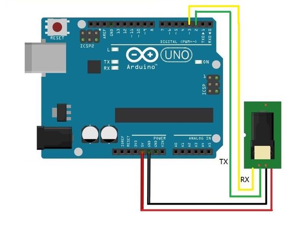
Connection diagram

The connection diagram of the FPM10A module and Arduino Uno must be connected together as in the figure above. We will go into more detail in the next step.
We connect components
Getting started with this module is incredibly easy due to the fact that it uses a serial port for communication. However, since the Arduino Uno only has one hardware serial port, you need to use the serial port via software using pins 2 and 3 to communicate with the fingerprint module (the hardware serial port is reserved for PC communication).

The ribbon cable that comes with the FPM10A module is not very hobby friendly as the wires sit in the case at 1.27mm pitch, so we cut off one side and then connected the wires to the jumpers.


Installing and Using the Library
The first step in using the FPM10A is to install the Adafruit Fingerprint library, which can be done using the Library Manager. Open the Arduino IDE and go to:
Sketch → Include Library → Manage Libraries

When the Library Manager loads a "Fingerprint" search, the first result should be the Adafruit Fingerprint Library. Install it.

After installing the library, it's time to create a new Arduino project. Click File → New , and then save the project in your own folder. At this point, open the project folder and copy the "fingerprint.h" file into it.

This is a special header file that was written to make the fingerprint library easier to use. The header file has only three functions:
- fingerprint_setup () - configures the serial port for 9600 baud and connects to the module;
- readFingerprint() - polling function that returns -1 if something went wrong, or returns information that a successful fingerprint was found
- enrollFingerprint (int id) - adds a fingerprint to the system with the assigned id "id".
To include this file in your project, simply use the include command as shown below:
#include "fingerprint.h"
The first function that needs to be called in setup() is fingerprint_setup(), which automatically connects to the module and confirms that everything is working.
Void setup() ( fingerprint_setup(); )
To add a new fingerprint, call the enrollFingerprint(id) function.
This will return -1 if it fails. Otherwise, the values indicate successful fingerprint enrollment. The identifier passed to this function a reference to the scanned fingerprint, and each fingerprint had a unique identification number.
enrollfingerprint(0x01);
Arduino code
You can copy the final sketch for our Arduino board below:
#include "fingerprint.h" void setup() ( fingerprint_setup(); ) void loop() ( // Create a new fingerprint entry enrollFingerprint(0x01); delay(1000); // Request entry Serial.println(" \nUSER LOGIN REQUEST...PLACE FINGER ONTO SENSOR \n"); while(readFingerprint() == -1); Serial.println(" \nACCESS GRANTED \n"); Serial.println(" \nFingerprint confidence: " + String (confidence) + "\n"); delay(3000); )
Principle of operation
When you enable this project, it will first ask you to place your finger on the scanner. If the scanner is capable of reading your fingerprints, it will ask you to remove and then replace your finger with the scanner. This should cause the scanner to successfully add your fingerprint to ID 1, and placing your finger on the scanner should result in system access.
This design can easily be extended to include solenoid locks and relays to allow authorized users to make changes and unlock the system. Once your project is complete - install the new scanner in doors, cabinets, safes, windows, electrical systems, computers and more!