What is a lan switch. Building a home network. What's smart about smart network switches? What are Bridges and Switches
The choice of router to use is determined by the Ethernet interfaces that match the switch technology at the center of the LAN. It is important to note that routers offer many LAN services and features.
Each LAN has a router, which is used as a gateway to connect the LAN to other networks. A LAN has one or more hubs or switches to connect end devices to the LAN.
Routers are the main devices used to connect networks. Each port on the router connects to a different network and routes packets between networks. Routers can break up broadcast and collision domains.
Routers are also used to connect networks that use different technologies. They can have both LAN and WAN interfaces.
The LAN interfaces of routers allow them to connect to LAN media. Typically these are UTP cable connections, but modules can be added to allow fiber optics. Depending on the series or model of routers, they may have several types of interfaces for WAN and LAN cable connections.

Intranet devices
To create a LAN, we must select appropriate devices to connect the end nodes to the network. The two most common devices used are hubs and switches.
Hub
The hub receives the signal, regenerates it and sends it to all ports. The use of hubs creates a logical bus. This means that the LAN uses the media in multi-access mode. The ports use a bandwidth sharing approach, which often results in reduced performance on the LAN due to collisions and recovery. Although multiple hubs can be connected, there will still be a single collision domain.
Hubs are less expensive than switches. A hub is usually chosen as an intermediary device for a very small LAN that has low bandwidth requirements, or where finances are limited.
Switch
The switch receives the frame and regenerates each bit of the frame to the corresponding destination port. This device is used to segment the network into multiple collision domains. Unlike a hub, a switch reduces the number of collisions on the LAN. Each port on the switch creates a separate collision domain. This creates a logical point-to-point topology for the device on each port. In addition, the switch provides dedicated bandwidth on each port, which can improve LAN performance. A LAN switch can also be used to connect network segments at different speeds.
In general, switches are chosen to connect devices to the LAN. Although a switch is more expensive than a hub, its improved performance and reliability make it cost-effective.
There is a whole range of switches available with a variety of features that allow you to connect many computers in a typical enterprise LAN setup.
Issues of building local networks seem very complex to non-specialist users due to the extensive terminological dictionary. Hubs and switches are imagined as complex equipment reminiscent of telephone PBXs, and creating a local home network becomes a reason to turn to specialists. In fact, the switch is not as scary as its name: both devices are elementary network nodes that have minimal functionality, do not require knowledge of installation and operation, and are quite accessible to everyone.
Definition
Hub— a network hub designed to connect computers into a single local network by connecting Ethernet cables.
Switch(switch) is a network switch designed to connect several computers into a local network via an Ethernet interface.
Comparison
As we can see from the definition, the difference between a hub and a switch is related to the type of device: hub and switch. Despite one task - organizing local network via Ethernet - devices approach this solution in different ways. A hub is a simple splitter that provides a direct connection between network clients. A switch is a more “smart” device that distributes data packets between clients in accordance with the request.
The hub, receiving a signal from one node, transmits it to all connected devices, and reception depends entirely on the recipient: the computer itself must recognize whether the packet is intended for it. Naturally, the answer assumes the same pattern. The signal pokes into all segments of the network until it finds one that will receive it. This circumstance reduces network throughput (and data exchange speed, respectively). The switch, receiving a data packet from the computer, sends it exactly to the address that was specified by the sender, relieving the network of load. A network organized through a switch is considered more secure: traffic exchange occurs directly between two clients, and others cannot process a signal that is not intended for them. Unlike a hub, a switch provides high throughput of the created network.
Logitec LAN-SW/PS Hub
Switch requires correct settings network card client computer: the IP address and subnet mask must match each other (the subnet mask specifies part of the IP address as the network address, and the other part as the client address). The hub does not require any settings, because it works at the physical level of the OSI network model, broadcasting a signal. The switch operates at the channel level, exchanging data packets. Another feature of the hub is the equalization of nodes in terms of data transfer speed, focusing on the lowest rates.
 Switch COMPEX PS2208B
 Conclusions website
- Hub is a hub, switch is a switch.
- The hub device is the simplest, the switch is more “intelligent”.
- The hub transmits the signal to all network clients, the switch only to the recipient.
- The performance of a network organized through a switch is higher.
- The switch provides a higher level of data transmission security.
- The hub operates at the physical layer of the OSI network model, the switch at the channel layer.
- The switch requires proper configuration of network cards of network clients.
In the overwhelming majority of home local networks, the only active equipment used is wireless router. However, if you need more than four wired connections, you will need to add a network switch (although today there are routers with seven to eight ports for clients). The second common reason for purchasing this equipment is more convenient network wiring. For example, you can install a switch near the TV, connect one cable from the router to it, and connect the TV itself, media player, game console and other equipment to other ports.
The simplest models of network switches have just a couple of key characteristics - the number of ports and their speed. And taking into account modern requirements and the development of the element base, we can say that if the goal of saving at any cost or some specific requirements is not the goal, it is worth buying models with gigabit ports. FastEthernet networks with a speed of 100 Mbps are of course used today, but it is unlikely that their users will encounter the problem of a lack of ports on the router. Although, of course, this is also possible, if you recall the products of some well-known manufacturers with one or two ports for a local network. Moreover, it would be appropriate to use a gigabit switch here to increase the performance of the entire wired local network.
In addition, when choosing, you can also take into account the brand, material and design of the case, the implementation of the power supply (external or internal), the presence and location of indicators and other parameters. Surprisingly, the characteristic of operating speed, which is familiar to many other devices, in this case makes virtually no sense, as was recently published. In data transfer tests, models of completely different categories and prices show the same results.
In this article, we decided to briefly talk about what can be interesting and useful in “real” Level 2 switches. Of course, this material does not pretend to be the most detailed and in-depth presentation of the topic, but, hopefully, it will be useful to those who are faced with more serious tasks or requirements when building their local network in an apartment, house or office than installing a router and setting up Wi-Fi. Fi. In addition, many topics will be presented in a simplified format, reflecting only the main points in the interesting and varied topic of switching network packets.
Previous articles in the series “Building home network"Available via links:
Besides, helpful information about building networks is available in this subsection.
Theory
First, let's remember how a “regular” network switch works.
This “box” is small in size, has several RJ45 ports for connecting network cables, a set of indicators and a power input. It works according to algorithms programmed by the manufacturer and does not have any user-accessible settings. The principle of “connect the cables - turn on the power - works” is used. Each device (more precisely, it network adapter) on the local network has a unique address - MAC address. It consists of six bytes and is written in the format "AA:BB:CC:DD:EE:FF" with hexadecimal digits. You can find it out programmatically or by looking at the information plate. Formally, this address is considered to be issued by the manufacturer at the production stage and is unique. But in some cases this is not the case (uniqueness is required only within the local network segment, and changing the address can be easily done in many operating systems). By the way, the first three bytes can sometimes reveal the name of the creator of the chip or even the entire device.
If for a global network (in particular the Internet), addressing devices and processing packets is carried out at the IP address level, then in each individual local network segment MAC addresses are used for this. All devices on the same local network must have different MAC addresses. If this is not the case, there will be problems with the delivery of network packets and network operation. Moreover, this low level of information exchange is implemented within the operating system network stacks and the user does not need to interact with it. Perhaps, in reality there are literally a couple of common situations where a MAC address can be used. For example, when replacing a router on a new device, specify the same MAC address WAN port that was on the old one. The second option is to enable MAC address filters on the router to block access to the Internet or Wi-Fi.
A regular network switch allows you to combine several clients to exchange network traffic between them. Moreover, not only one computer or other client device can be connected to each port, but also another switch with its own clients. Roughly, the switch’s operation diagram looks like this: when a packet arrives at a port, it remembers the sender’s MAC and writes it into the “clients on this physical port” table, the recipient’s address is checked against other similar tables, and if it is in one of them, the packet is sent to corresponding physical port. Additionally, algorithms are provided for eliminating loops, searching for new devices, checking whether a device has changed a port, and others. To implement this scheme, no complex logic is required; everything works on fairly simple and inexpensive processors, so, as we said above, even low-end models are able to show maximum speeds.
Managed or sometimes called “smart” switches are much more complex. They are able to use more information from network packets to implement more complex algorithms for processing them. Some of these technologies may also be useful for “high-end” or more demanding home users, as well as for solving some special tasks.
Second-level switches (Level 2, data link layer) are capable of taking into account, when switching packets, information contained within certain fields of network packets, in particular VLAN, QoS, multicast and some others. This is the option we will talk about in this article. More complex models of the third level (Level 3) can already be considered routers, since they operate with IP addresses and work with third-level protocols (in particular RIP and OSPF).
Please note that there is no single universal and standard set of capabilities for managed switches. Each manufacturer creates its own product lines based on its understanding of consumer requirements. So in each case it is worth paying attention to the specifications of a particular product and their compliance with the tasks set. Of course, there is no talk of any “alternative” firmware with wider capabilities here.
As an example, we use the Zyxel GS2200-8HP device. This model has been on the market for a long time, but is quite suitable for this article. Modern products in this segment from Zyxel generally provide similar capabilities. In particular, the current device of the same configuration is offered under the article number GS2210-8HP.
The Zyxel GS2200-8HP is an eight-port (there is also a 24-port version in the series) managed gigabit Level 2 switch, which also includes PoE support and combined RJ45/SFP ports, as well as some more advanced features. high levels switching

In terms of its format, it can be called a desktop model, but the package includes additional mounting hardware for installation in a standard 19″ rack. The body is made of metal. On the right side we see a ventilation grille, and on the opposite side there are two small fans. At the back there is only a network cable input for the built-in power supply.
All connections, traditionally for such equipment, are made from the front side for ease of use in racks with patch panels. On the left there is an insert with the manufacturer's logo and the illuminated name of the device. Next are the indicators - power, system, alarm, status/activity and power LEDs for each port.
Following are the main eight network connectors, and after them two RJ45 and two SFP duplicating them with own indicators. Such solutions are another characteristic feature similar devices. Typically, SFP is used to connect optical communication lines. Their main difference from the usual twisted pair is the ability to work over significantly longer distances - up to tens of kilometers.

Due to the fact that different types of physical lines can be used here, SFP standard ports are installed directly in the switch, into which special transceiver modules must be additionally installed, and optical cables are connected to them. At the same time, the resulting ports do not differ in their capabilities from the others, of course, except for the lack PoE support. They can also be used in port trunking mode, scenarios with VLANs and other technologies.
The console serial port completes the description. It is used for service and other operations. In particular, we note that there is no reset button, which is typical for home equipment. In severe cases of loss of control, you will have to connect via the serial port and reload the entire configuration file in debug mode.
The solution supports administration via the Web and command line, firmware updates, 802.1x protocol to protect against unauthorized connections, SNMP for integration into monitoring systems, packets with a size of up to 9216 bytes (Jumbo Frames) to increase network performance, second-layer switching services, stacking capabilities for ease of administration.
Of the eight main ports, half support PoE+ with up to 30 W per port, and the remaining four support PoE with 15.4 W. The maximum power consumption is 230 W, of which up to 180 W can be supplied via PoE.
The electronic version of the user manual has more than three hundred pages. So the functions described in this article represent only a small part of the capabilities of this device.
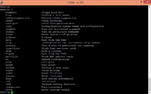
Management and control
Unlike simple network switches, “smart” ones have tools for remote configuration. Their role is most often played by the familiar Web interface, and for “real administrators” access to the command line with its own interface via telnet or ssh is provided. A similar command line can be obtained through a connection to the serial port on the switch. In addition to habit, working with command line has the advantage of convenient automation using scripts. There is also support for the FTP protocol, which allows you to quickly download new firmware files and manage configurations.
For example, you can check the status of connections, manage ports and modes, allow or deny access, and so on. In addition, this option is less demanding on bandwidth (requires less traffic) and the equipment used for access. But in the screenshots, of course, the Web interface looks more beautiful, so in this article we will use it for illustrations. Security is provided by a traditional administrator username/password, there is support for HTTPS, and you can also configure additional restrictions on access to switch management.

Note that, unlike many home devices, the interface has an explicit button for saving the current switch configuration to its non-volatile memory. Also on many pages you can use the Help button to call up contextual help.
Another option for monitoring the operation of the switch is to use the SNMP protocol. Using specialized programs, you can obtain information about the hardware status of the device, such as temperature or loss of a link on a port. For large projects, it will be useful to implement a special mode for managing several switches (a cluster of switches) from a single interface - Cluster Management.
The minimum initial steps to start up the device typically include updating the firmware, changing the administrator password, and configuring the switch's own IP address.

In addition, it is usually worth paying attention to options such as network name, synchronization of the built-in clock, sending the event log to an external server (for example, Syslog).
When planning the network layout and switch settings, it is recommended to calculate and think through all the points in advance, since the device does not have built-in controls for blocking and contradictions. For example, if you “forget” that you previously configured port aggregation, then VLANs with their participation may behave completely differently than required. Not to mention the possibility of losing connection with the switch, which is especially unpleasant when connecting remotely.
One of the basic “smart” functions of switches is support for network port aggregation technologies. Also used for this technology are terms such as trunking, bonding, and teaming. In this case, clients or other switches are connected to this switch not with one cable, but with several at once. Of course, this requires having several network cards on your computer. Network cards can be either separate or made in the form of a single expansion card with several ports. Typically in this scenario we are talking about two or four links. The main tasks solved in this way are increasing speed network connection and increasing its reliability (duplication). A switch can support several such connections at once, depending on its hardware configuration, in particular, the number of physical ports and processor power. One option is to connect a pair of switches in this way, which will increase the overall network performance and eliminate bottlenecks.
To implement the scheme, it is advisable to use network cards that explicitly support this technology. But in general, the implementation of port aggregation can be done at the software level. This technology most often implemented through the open LACP/802.3ad protocol, which is used to monitor the status of links and manage them. But there are also private options from individual vendors.
At the level operating system clients, after appropriate configuration, usually a new standard network interface simply appears, which has its own MAC and IP addresses, so that all applications can work with it without any special actions.
Fault tolerance is ensured by having multiple physical connections between devices. If the connection fails, traffic is automatically redirected along the remaining links. Once the line is restored, it will start working again.
As for increasing speed, the situation here is a little more complicated. Formally, we can assume that productivity is multiplied according to the number of lines used. However, the actual increase in data transmission and reception speed depends on specific tasks and applications. In particular, if we are talking about such a simple and common task as reading files from a network storage device on a computer, then it will not gain anything from combining ports, even if both devices are connected to the switch by several links. But if port trunking is configured to network storage and several “regular” clients will access it simultaneously, then this option will already receive a significant gain in overall performance.
Some examples of use and test results are given in the article. Thus, we can say that the use of port aggregation technologies at home will be useful only if there are several fast clients and servers, as well as a sufficiently high load on the network.
Setting up port aggregation on a switch is usually straightforward. In particular, on the Zyxel GS2200-8HP required parameters are located in the Advanced Application - Link Aggregation menu. Total this model supports up to eight groups. There are no restrictions on the composition of groups - you can use any physical port in any group. The switch supports both static port trunking and LACP.

On the status page you can check the current assignments by group.

On the settings page, active groups and their type are indicated (used to select the packet distribution scheme across physical links), as well as the assignment of ports to the required groups.

If necessary, enable LACP for the required groups on the third page.
Next, you need to configure similar settings on the device on the other side of the link. In particular, on a QNAP network drive this is done as follows - go to the network settings, select ports and the type of their connection.

After this, you can check the status of the ports on the switch and evaluate the effectiveness of the solution in your tasks.
VLAN
In a typical local network configuration, network packets “walking” through it use a common physical environment, like flows of people at subway transfer stations. Of course, switches, in a certain sense, prevent “foreign” packets from reaching the interface of your network card, but some packets, such as broadcast packets, can penetrate any corner of the network. Despite the simplicity and high speed of this scheme, there are situations when, for some reason, you need to separate certain types of traffic. This may be due to security requirements or the need to meet performance or prioritization requirements.
Of course, these issues can be resolved by creating a separate segment of the physical network - with its own switches and cables. But this is not always possible to implement. This is where VLAN (Virtual Local Area Network) technology can come in handy - logical or virtual local computer network. It may also be referred to as 802.1q.
To a rough approximation, the operation of this technology can be described as the use of additional “tags” for each network packet when it is processed in the switch and on the end device. In this case, data exchange only works within a group of devices with the same VLAN. Since not all equipment uses VLANs, the scheme also uses operations such as adding and removing tags from a network packet as it passes through the switch. Accordingly, it is added when a packet is received from a “regular” physical port for sending through the VLAN network, and removed when it is necessary to transmit a packet from the VLAN network to a “regular” port.
As an example of the use of this technology, we can recall multi-service connections of operators - when you get access to the Internet, IPTV and telephony via one cable. This was previously found in ADSL connections, and today is used in GPON.

The switch in question supports the simplified “Port-based VLAN” mode, when the division into virtual networks is carried out at the level of physical ports. This scheme is less flexible than 802.1q, but may be suitable in some configurations. Note that this mode is mutually exclusive with 802.1q, and for selection there is a corresponding item in the Web interface.

To create a VLAN according to the 802.1q standard, on the Advanced Applications - VLAN - Static VLAN page, specify the name of the virtual network, its identifier, and then select the ports involved and their parameters. For example, when connecting regular clients, it is worth removing VLAN tags from the packets sent to them.

Depending on whether this is a client connection or a switch connection, you need to configure the required options on the Advanced Applications - VLAN - VLAN Port Settings page. In particular, this concerns adding tags to packets arriving at the port input, allowing packets without tags or with other identifiers to be broadcast through the port, and isolating the virtual network.
Access control and authentication
Ethernet technology initially did not support access control to the physical medium. It was enough to plug the device into the switch port - and it began to work as part of the local network. In many cases this is sufficient, since the protection is provided by the complexity of direct physical connection to the network. But today the requirements for network infrastructure have changed significantly and the implementation of the 802.1x protocol is increasingly found in network equipment.
![]()
In this scenario, when connecting to a switch port, the client provides its authentication data and without confirmation from the access control server, no information exchange occurs with the network. Most often, the scheme involves the presence of an external server, such as RADIUS or TACACS+. Using 802.1x also provides additional features on control networking. If in the standard scheme you can “bind” only to the client’s hardware parameter (MAC address), for example, to issue an IP, set speed limits and access rights, then working with user accounts will be more convenient in large networks, since it allows for client mobility and other top level features.

A RADIUS server on a QNAP NAS was used for testing. It is designed as a separately installed package and has its own user base. It is quite suitable for this task, although in general it has few capabilities.

The client was a computer with Windows 8.1. To use 802.1x on it, you need to enable one service and after that a new tab appears in the properties of the network card.

Note that in this case we are talking exclusively about controlling access to the physical port of the switch. In addition, do not forget that it is necessary to ensure constant and reliable access of the switch to the RADIUS server.
To implement this feature, the switch has two functions. The first, the simplest, allows you to limit incoming and outgoing traffic on a specified physical port.

This switch also allows you to use prioritization for physical ports. In this case, there are no hard limits for speed, but you can select devices whose traffic will be processed first.
The second is included in more general scheme with the classification of switched traffic according to various criteria and is only one of the options for its use.

First, on the Classifier page, you need to define traffic classification rules. They apply Level 2 criteria - in particular MAC addresses, and in this model Level 3 rules can also be applied - including protocol type, IP addresses and port numbers.

Next, on the Policy Rule page, you specify the necessary actions with the traffic “selected” according to the selected rules. The following operations are provided here: setting a VLAN tag, limiting the speed, outputting a packet to a given port, setting a priority field, dropping a packet. These functions allow, for example, to limit data exchange rates for client data or services.

More complex schemes may use 802.1p priority fields in network packets. For example, you can tell the switch to handle telephony traffic first and give browser browsing the lowest priority.
PoE
Another possibility that is not directly related to the packet switching process is to provide power to client devices through network cable. This is often used to connect IP cameras, telephones and wireless access points, which reduces the number of wires and simplifies switching. When choosing such a model, it is important to take into account several parameters, the main one of which is the standard used by the client equipment. The fact is that some manufacturers use their own implementations, which are incompatible with other solutions and can even lead to breakdown of “foreign” equipment. It is also worth highlighting “passive PoE”, when power is transmitted with relatively low voltage without feedback and control of the recipient.
A more correct, convenient and universal option would be to use “active PoE”, operating according to the 802.3af or 802.3at standards and capable of transmitting up to 30 W (higher values are also found in new versions of the standards). In this scheme, the transmitter and receiver exchange information with each other and agree on the necessary power parameters, in particular power consumption.

To test this, we connected an Axis 802.3af PoE compatible camera to the switch. On front panel The switch lights up the corresponding power indicator for this port. Then, through the Web interface, we will be able to monitor the consumption status by port.

Also interesting is the ability to control the power supply to the ports. Because if the camera is connected with one cable and is located in a hard-to-reach place, to reboot it, if necessary, you will need to disconnect this cable either on the camera side or in the wiring closet. And here you can log into the switch remotely by anyone in an accessible way and just uncheck “supply power” and then put it back. In addition, in the PoE settings, you can configure the priority system for providing power.
As we wrote earlier, the key field of network packets in this equipment is the MAC address. Managed switches often have a set of services designed to use this information.

For example, the model under consideration supports static assignment of MAC addresses to a port (usually this operation occurs automatically), filtering (blocking) of packets by source or recipient MAC addresses.

In addition, you can limit the number of client MAC address registrations on a switch port, which can also be considered an additional security option.
Most layer 3 network packets are usually unidirectional - they go from one addressee to one recipient. But some services use multicast technology, when one package has several recipients at once. The most famous example is IPTV. The use of multicast here allows you to significantly reduce bandwidth requirements when it is necessary to deliver information a large number clients. For example, multicast of 100 TV channels with a flow of 1 Mbit/s will require 100 Mbit/s for any number of clients. If we use standard technology, then 1000 clients would require 1000 Mbit/s.

We will not go into the details of how IGMP works; we will only note the possibility of fine-tuning the switch for efficient work under heavy loads of this type.

IN complex networks Special protocols can be used to control the path of network packets. In particular, they make it possible to eliminate topological loops (“looping” of packets). The switch in question supports STP, RSTP and MSTP and has flexible settings for their operation.

Another feature in demand in large networks is protection against situations such as “broadcast storm”. This concept characterizes a significant increase in broadcast packets in the network, blocking the passage of “normal” useful traffic. Most in a simple way The way to combat this is to set limits on the processing of a certain number of packets per second for switch ports.

Additionally, the device has Error function Disable. It allows the switch to shut down ports if it detects excessive service traffic. This helps maintain productivity and ensure automatic recovery work after fixing the problem.

Another task, more related to security requirements, is monitoring all traffic. In normal mode, the switch implements a scheme to send packets only directly to their recipients. It is impossible to “catch” a “foreign” packet on another port. To implement this task, port mirroring technology is used - control equipment is connected to selected switch ports and all traffic from specified other ports is configured to be sent to this port.

The IP Source Guard and DHCP Snooping ARP Inspection functions are also aimed at increasing security. The first allows you to configure filters involving MAC, IP, VLAN and port number through which all packets will pass. The second protects the DHCP protocol, the third automatically blocks unauthorized clients.
Conclusion
Of course, the capabilities described above represent only a fraction of the network switching technologies available on the market today. And even from this small list, not all of them can find real use among home users. Perhaps the most common are PoE (for example, to power network video cameras), port aggregation (in the case of a large network and the need for fast traffic exchange), traffic control (to ensure the operation of streaming applications when high load per channel).
Of course, it is not at all necessary to use business-level devices to solve these problems. For example, in stores you can find a regular switch with PoE, port aggregation is also found in some top-end routers, prioritization is also starting to be found in some models with fast processors and high-quality software. But, in our opinion, the option of purchasing more professional equipment, including on the secondary market, can also be considered for home networks with increased requirements for performance, security and manageability.
By the way, there is actually another option. As we said above, in all “smart” switches there can be a different amount of “mind” directly. And many manufacturers have a series of products that fit well into the home budget and at the same time are able to provide many of the features described above. As an example, we can mention the Zyxel GS1900-8HP.

This model has a compact metal case and an external power supply, it has eight gigabit ports with PoE, and a Web interface is provided for configuration and management.

The device firmware supports port aggregation with LACP, VLAN, port rate limiting, 802.1x, port mirroring and other functions. But unlike the “real managed switch” described above, all this is configured exclusively through the Web interface and, if necessary, even using an assistant.

Of course, we are not talking about the similarity of this model to the device described above in terms of its capabilities as a whole (in particular, there are no traffic classification tools and Level 3 functions here). Rather, it is simply a more suitable option for the home user. Similar models can be found in the catalogs of other manufacturers.
03/18/1997 Dmitry Ganzha
Switches occupy a central place in modern local area networks. TYPES OF SWITCHING SWITCHING HUBS METHODS OF PACKET PROCESSING RISC AND ASIC ARCHITECTURE OF HIGH-CLASS SWITCHES BUILDING VIRTUAL NETWORKS THIRD LEVEL SWITCHING CONCLUSION Switching is one of the most popular.
modern technologies
Switches occupy a central place in modern local area networks. Switching is one of the most popular modern technologies. Switches are displacing bridges and routers to the periphery of local networks, leaving behind them the role of organizing communication through. This popularity of switches is primarily due to the fact that they allow, through microsegmentation, to increase network performance compared to shared networks with the same nominal bandwidth. In addition to dividing the network into small segments, switches make it possible to organize connected devices into logical networks and easily regroup them when necessary; in other words, they allow you to create virtual networks.
What is a switch? According to the IDC definition, “a switch is a device designed in the form of a hub and acting as a high-speed multiport bridge; the built-in switching mechanism allows segmentation of the local network and allocation of bandwidth to end stations in the network” (see M. Kulgin’s article “Build a network, plant a tree..." in the February issue LAN). However, this definition applies primarily to frame switches.
TYPES OF SWITCHING
Switching usually refers to four different technologies - configuration switching, frame switching, cell switching, and frame-to-cell conversion.
Configuration switching is also known as port switching, where a specific port on a smart hub module is assigned to one of the internal Ethernet segments (or Token Ring). This assignment is made remotely via program control network when connecting or moving users and resources on the network. Unlike other switching technologies, this method does not improve the performance of the shared LAN.
Frame switching, or local network switching, uses standard formats Ethernet frames(or Token Ring). Each frame is processed by the nearest switch and transmitted further across the network directly to the recipient. As a result, the network turns into a set of parallel high-speed direct channels. We will look at how frame switching is carried out inside a switch below using the example of a switching hub.
Cell switching is used in ATM. The use of small fixed-length cells makes it possible to create low-cost, high-speed switching structures at the hardware level. Both frame switches and mesh switches can support multiple independent workgroups regardless of their physical connection (see the section "Building virtual networks").
The conversion between frames and cells allows, for example, a station with an Ethernet card to communicate directly with devices on an ATM network. This technology is used to emulate a local network.
In this lesson we will be primarily interested in frame switching.
SWITCHING HUBS
The first switching hub, called EtherSwictch, was introduced by Kalpana. This hub made it possible to reduce network contention by reducing the number of nodes in a logical segment using microsegmentation technology. Essentially, the number of stations in one segment was reduced to two: the station initiating the request and the station responding to the request. No other station sees the information transmitted between them. Packets are transmitted as if through a bridge, but without the delay inherent in a bridge.
In a switched Ethernet network, each member of a group of multiple users can simultaneously be guaranteed throughput 10 Mbit/s. The best way to understand how such a concentrator works is by analogy with an ordinary old telephone switch, in which the participants in the dialogue are connected coaxial cable. When a subscriber called “eternal” 07 and asked to be connected to such and such a number, the operator first of all checked whether the line was available; if so, he connected the participants directly using a piece of cable. No one else (with the exception of the intelligence services, of course) could hear their conversation. After the call ended, the operator disconnected the cable from both ports and waited for the next call.
Switching hubs operate in a similar way (see Figure 1): they forward packets from an input port to an output port through the switch fabric. When a packet arrives at an input port, the switch reads its MAC address (i.e., layer 2 address) and it is immediately forwarded to the port associated with that address. If the port is busy, the packet is placed in a queue. Essentially, a queue is a buffer on an input port where packets wait for the desired port to become free. However, the buffering methods are slightly different.
Picture 1.
Switching hubs function similarly to older telephone switches: they connect an input port directly to an output port through a switch fabric.
PACKET PROCESSING METHODS
In end-to-end switching (also called in-flight switching and bufferless switching), the switch reads only the address of the incoming packet. The packet is transmitted further regardless of the absence or presence of errors in it. This can significantly reduce packet processing time, since only the first few bytes are read. Therefore, it is up to the receiving party to identify defective packets and request their retransmission. However, modern cable systems reliable enough that the need for retransmission on many networks is minimal. However, no one is immune from errors in the event of cable damage, malfunction network card or interference from an external electromagnetic source.
When switching with intermediate buffering, the switch, receiving a packet, does not transmit it further until it reads it completely, or at least reads all the information it needs. It not only determines the recipient's address, but also checks the checksum, i.e. it can cut off defective packets. This allows you to isolate the error-producing segment. Thus, buffer-and-forward switching emphasizes reliability rather than speed.
Apart from the above two, some switches use a hybrid method. Under normal conditions, they provide end-to-end switching, but monitor the number of errors by checking checksums. If the number of errors reaches a specified threshold, they enter switching mode with forward buffering. When the number of errors decreases to an acceptable level, they return to end-to-end switching mode. This type of switching is called threshold or adaptive switching.
RISC AND ASIC
Often, buffer-forward switches are implemented using standard RISC processors. One advantage of this approach is that it is relatively inexpensive compared to ASIC switches, but it is not very good for specialized applications. Switching in such devices is carried out using software, therefore their functionality can be changed by upgrading the installed software. Their disadvantage is that they are slower than ASIC-based switches.
Switches with ASIC integrated circuits are designed to perform specialized tasks: all their functionality is “hardwired” into the hardware. There is also a drawback to this approach: when modernization is necessary, the manufacturer is forced to rework the circuit. ASICs typically provide end-to-end switching. The switch fabric ASIC creates dedicated physical paths between an input and output port, as shown in .
ARCHITECTURE OF HIGH-CLASS SWITCHES
High-end switches are typically modular in design and can perform both packet and cell switching. Modules of such a switch carry out switching between networks different types, including Ethernet, Fast Ethernet, Token Ring, FDDI and ATM. In this case, the main switching mechanism in such devices is the ATM switching structure. We will look at the architecture of such devices using the Bay Networks Centillion 100 as an example.
Switching is accomplished using the following three hardware components (see Figure 2):
 (1x1)
(1x1)
Figure 2.
Cell switching is increasingly being used in high-end switches due to its high speed and ease of migration to ATM.
Each switch module has I/O ports, buffer memory, and a CellManager ASIC. In addition, each LAN module also has a RISC processor to perform frame switching between local ports and a packet assembler/disassembler to convert frames and cells into each other. All modules can independently switch between their ports, so that only traffic destined for other modules is sent through the backplane.
Each module maintains its own table of addresses, and the main control processor combines them into one common table, so that an individual module can see the network as a whole. If, for example, an Ethernet module receives a packet, it determines who the packet is addressed to. If the address is in the local address table, then the RISC processor switches the packet between local ports. If the destination is on another module, then the assembler/disassembler converts the packet into cells. The CellManager specifies a destination mask to identify the module(s) and port(s) to which the cells payload is destined. Any module whose board mask bit is specified in the destination mask copies the cell to local memory and transmits the data to the corresponding output port in accordance with the specified port mask bits.
BUILDING VIRTUAL NETWORKS
In addition to increasing productivity, switches allow you to create virtual networks. One method of creating a virtual network is to create a broadcast domain through a logical connection of ports within the physical infrastructure communication device(this can be either an intelligent hub - configuration switching, or a switch - frame switching). For example, the odd ports of an eight-port device are assigned to one virtual network, and the even ports are assigned to another. As a result, a station in one virtual network becomes isolated from stations in another. The disadvantage of this method of organizing a virtual network is that all stations connected to the same port must belong to the same virtual network.
Another method for creating a virtual network is based on the MAC addresses of connected devices. With this method of organizing a virtual network, any employee can connect, for example, his laptop to any switch port, and it will automatically determine whether its user belongs to a particular virtual network based on the MAC address. This method also allows users connected to the same switch port to belong to different virtual networks. Read more about virtual networks see the article by A. Avduevsky “Such real virtual networks” in the March issue of LAN for this year.
LEVEL 3 SWITCHING
For all their advantages, switches have one significant drawback: they are unable to protect the network from avalanches of broadcast packets, and this leads to unproductive network load and increased response time. Routers can monitor and filter unnecessary broadcast traffic, but they are orders of magnitude slower. Thus, according to Case Technologies documentation, the typical performance of a router is 10,000 packets per second, and this cannot be compared with the same indicator of a switch - 600,000 packets per second.
As a result, many manufacturers have begun to build routing capabilities into switches. To prevent the switch from slowing down significantly, various methods are used: for example, both Layer 2 switching and Layer 3 switching are implemented directly in hardware(in ASIC integrated circuits). Different manufacturers call this technology differently, but the goal is the same: the routing switch must perform Layer 3 functions at the same speed as Layer 2 functions. An important factor is the price of such a device per port: it should also be low, like that of switches (see article by Nick Lippis in the next issue of LAN magazine).
CONCLUSION
Switches are both structurally and functionally very diverse; It is impossible to cover all their aspects in one short article. In the next tutorial, we'll take a closer look at ATM switches.
Dmitry Ganzha is the executive editor of LAN. He can be contacted at: [email protected].
Switches in the local network