Do-it-yourself magnetic antenna made of coaxial cable. Magnetic antenna from VA3LLZ from Toronto. Experiments with magnetic loop antennas
The good results obtained with the "Magnetic Loop" antenna prompted I1ARZ to try building an antenna for the low bands. Initially, he intended to build a circular loop antenna (Fig. 1) with a perimeter of about 10.5 m, which is a quarter of a wavelength on the 7 MHz band. For this purpose, a loop was made from copper tube 40 mm in diameter with thin walls However, in the course of the work it turned out that bending and unbending tubes of this size is quite difficult, and the shape of the antenna was changed from round to square. Some decrease in efficiency is offset by a significant simplification of manufacturing.
For the range of 1.8 ... 7.2 MHz, you can use a copper tube with a diameter of 25 ... 40 mm. You can also use duralumin tubes, but not everyone has the ability to weld in argon. After assembly, the entire antenna frame is covered with several layers of protective varnish.
The tuning capacitor is very important for the proper operation of the antenna. He must be good quality, with a large gap between the plates. A vacuum capacitor with a capacity of 7 ... 1000 pF with an allowable voltage of 7 kV is used. It can withstand more than 100 W of power in the antenna, which is quite enough. In the case where the 160 m range is used, the capacitance should reach 1600 pF.
The square-shaped loop is assembled from four copper tubes 2.5 m long and 40 mm in diameter. The tubes are connected together using four copper water pipes. The tubes are welded to the knees. Opposite sides of the frame should be parallel to each other. A piece 100 mm long is cut out in the middle of the upper tube, a Teflon spindle is inserted into the cutout and fixed on both sides with clamps and screws. The diagonal of the loop is 3.4 m, the total length is 10.67 m (together with copper plates 50 mm wide, to which the ends of the tube are attached, providing the connection of a tuning capacitor). To ensure reliable contact, the plates must be welded to the ends of the tube after they are attached.

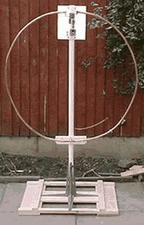
Figure 2 shows the construction of the frame together with the base and the carrier mast. The mast must be dielectric, for example, made of fiberglass rod. You can also use a plastic tube. In the lower part, the frame is fixed on the carrier mast with steel clamps (Fig. 3).
To strengthen the lower horizontal piece of the frame, a heated copper tube of a slightly larger diameter is pulled over it over a length of approximately 300 mm. The motor that rotates the condenser is mounted on a steel pipe at a height of about 2 m above the roof. To stiffen the entire structure, at least three stretch marks are installed below the motor.
The easiest way is to match the antenna frame and the power line with a coil coaxial cable type RG8 or RG213 The coil diameter is determined empirically (about 0.5 m). Connection of the inner core and cable sheath is carried out in accordance with Fig. 4
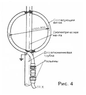
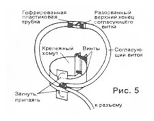
After the matching coil is set to the lowest SWR, a corrugated plastic tube is pulled over the connection point to protect it from precipitation. At the end of the matching coil, you need to install a coaxial connector. In the place of the lower fastening of the matching coil, a piece of copper tape is threaded under the fastening duralumin clamp, which, after bending, is soldered to the cable shielding sheath. It is needed for good electrical contact with a grounded duralumin tube (Fig. 5). In the upper part, the matching coil is attached to the dielectric mast with rubber clamps.
If the antenna is located on a roof, for remote control tuning capacitor requires a DC motor drive unit. For this purpose, any small tape recorder motor with a small gearbox is suitable. The motor is connected to the capacitor shaft with an isolating clutch or a plastic gear. The capacitor shaft must also be mechanically connected to a 22 kΩ group A potentiometer. The position of the tuning capacitor is determined from below with this potentiometer. The complete diagram of the control unit is shown in Fig.6.

Naturally, the potentiometer must be placed on the same side as the motor, connecting them with two plastic gears or a friction gear. The entire tuning unit is placed in a hermetically sealed plastic case (or tube). The cable to the motor and the wires from the potentiometer are routed along the fiberglass support mast. If the antenna is located near the radio station (for example, on a balcony), tuning can be done directly using a long roller on an insulated handle.
Tuning Capacitor Placement
As already mentioned, the fixed and movable parts of the tuning capacitor are attached to the upper, cut part of the frame using two copper plates about 0.5 mm thick, 50 mm wide and 300 mm long each. The tuning capacitor is placed in a plastic tube, which is attached to a vertical fiberglass carrier mast (Fig. 7). Top part the frame is connected with a Teflon spindle and attached to the supporting fiberglass pole with U-bolts.
Setting
Set TRX to dummy load, switch TRX output to antenna. Do not use an antenna tuner in this experiment. With reduced output power, start rotating the capacitor until a minimum SWR is obtained. If you cannot achieve a low SWR in this way, try to slightly deform the matching coil. If the SWR does not improve, the coil must either be lengthened or shortened. With a little patience, in the ranges of 1.8 ... 7 MHz, you can achieve an SWR of 1 ... 1.5. The following SWR values \u200b\u200bof 1.5 at 40 m, 1.2 at 80 m and 1.1 at 160 m were achieved.
results
Antenna tuning is very "sharp". In the range of 160 m, the antenna bandwidth is units of kilohertz. Directional pattern (DN) - almost circular. Figure 8 shows the RPs in the horizontal plane for various vertical radiation angles.
The antenna gives the best results in the range of 40 m. At a power of 50 W, the author established many contacts with the east coast of the USA with a report of 59. At distances up to 500 km, reports were 59 + 20 ... 25 dB during the day. The antenna is also very good at reception, since a sufficiently “sharp” tuning reduces the noise and signals of strong stations operating nearby. The antenna works surprisingly well in the 160 m range. From the first attempts, communication was established at a distance of over 500 km with a report of 59 + 20 dB. From a fundamental point of view, in this range the antenna efficiency is much lower than in the 40 m range (see table).

Final remarks
- The antenna should be placed as far away from large metal objects as possible, such as fences, metal poles, drainpipes, etc.
- The antenna is not recommended to be placed indoors, since the antenna frame emits a strong magnetic field during transmission, which is harmful to health.
- When working with powers above 100 W, the frame heats up under the influence of a large current.
- At the highest range, the antenna polarization is horizontal.
The table above shows the main electrical parameters of the antenna in the indicated ranges. A similar antenna can be built for higher frequency ranges, respectively, reducing the size of the frame and the capacitance of the tuning capacitor.
At the mention of a magnetic antenna, those on a ferrite rod somehow immediately come to mind, and this is partly correct. These are all variations of the same type of device. A loop antenna is called magnetic, the perimeter of which is much smaller than the wavelength. The well-known zigzag and bi-square (almost the same) are also relatives of the technology in question. And they have absolutely nothing to do with antennas on a magnetic base. It's just a mounting method, nothing more. The magnetic base for the antenna securely holds it on the roof of any car. We are talking today about a special design. The whole beauty of magnetic antennas is that it is possible to provide a relatively large gain at relatively long wavelengths. In this case, the size of the magnetic antenna is quite small. Let's discuss our title and tell you how a do-it-yourself magnetic antenna can be made.
Magnetic Antennas
It is known from theory that almost no radiation occurs in an oscillatory circuit of an inductor and a capacitor. It is all closed, and the wave can swing at the resonant frequency for an arbitrarily long time, fading, due to the presence of active resistance. Yes, the circuit elements, inductance and capacitance, in general, have a purely reactive (imaginary) impedance. Moreover, the size depends on the frequency according to a rather uncomplicated law. This is something like the product of the circular frequency (2 P f) by the value of the inductance or capacitance, respectively. And now, at a certain value, the imaginary components opposite in sign become equal. As a result, the impedance becomes purely active, ideally it is zero.
In reality, the beats are still damped, because in practice each circuit is characterized by a quality factor. Recall that the impedance consists of a purely active (real) part, such as resistors, and an imaginary one. The latter include capacitances whose resistance is imaginary negative and inductances with positive imaginary resistance. Now imagine that in the circuit of the capacitor plates they began to part until they were at opposite ends of the inductance. This is called a vibrator (dipole) Hertz, and is a kind of shortened half-wave and other types of vibrators.
If we take and turn the coil into a single ring, then we get the simplest magnetic antenna. This is a very simplistic interpretation, but that's pretty much how it is. Moreover, the signal is taken from the opposite side of the capacitor through an amplifier on field-effect transistors. This ensures high sensitivity of the device. Well, the antenna on a ferrite rod is a kind of magnetic, only it has many rings instead of one. This type of device got its name for its high sensitivity to the magnetic component of the wave. In particular, when working on a transmission, it is precisely it that is generated, generating a response of the electric field.
The directivity maximum corresponds to the axis of the rod. And both directions are equal. Due to the small perimeter of the loop antenna relative to the wavelength, its resistance is quite low. It can be not just 1 ohm, but even fractions of an ohm. An approximate value can be estimated by the formula:
R = 197 (U / λ) 4 ohm.
U is the perimeter in meters, in the same units as the wavelength λ. Finally, R is the resistance to radiation, do not confuse it with the active one that the tester shows. This parameter is used when calculating the amplifier for load matching. Therefore, for ferrite antennas, this value must be multiplied by the square of the number of turns.
Properties of magnetic antennas
And now let's see how to make a magnetic antenna yourself. First you need to determine the circumference and capacitance of the trimmer capacitor. In fact, the features of a magnetic antenna are such that it requires mandatory coordination, but more on that some other time. The fact is that the hallmark is the incredible number of options for carrying out this operation, so that a separate topic for conversation emerges.

The length of the perimeter of the magnetic antenna ranges from 0.123 to 0.246 λ. If you want to cover this entire range, then you need to choose the right capacitor. In free space and a magnetic antenna, the radiation pattern is in the form of a torus, which can be observed by placing the coil parallel to the ground. The polarization will then be linear horizontal. That is, it is an excellent option for receiving television broadcasts. The disadvantage is that the angle of elevation of the petal depends on the height of the suspension. It is believed that for the distance to the Earth λ it will be 14 degrees. And this impermanence is a negative quality. But for radio, magnetic antennas are used quite often.
The gain is 1.76 dBi, which is 0.39 less than that of the half wave vibrator. But the size of the latter for this frequency will be tens of meters - well, where can you put such a hulk? Draw your own conclusions. Our magnetic antenna is not that big (the perimeter can be 2 meters for a wavelength of 20 meters, which is less than a meter across). For comparison, at a frequency of 34 MHz, which is well known to truckers thanks to walkie-talkies, the wavelength is 8.8 meters. At the same time, everyone knows that not every Kamaz will fit a good half-wave vibrator. And, by the way, earlier we already gave a description of the design of the loop antenna formed by the rubber gasket of the rear window of a VAZ car. For all its small dimensions, the device worked quite well.
By the way, this design is considered more pragmatic than typical whip antennas for cars, where tuning is done by changing the inductance. There are fewer losses. In addition, the radiation pattern covers fairly high elevation angles, almost to the vertical. In the case of a whip antenna, this possibility is not available.
But how to choose the right circumference? With its increase, the gain increases. That is, it must satisfy the condition given above, and be as large as possible. At the same time, do not forget that sometimes you need to block several frequencies. In addition, as the perimeter grows, the bandwidth of the device increases. I must say, with a typical channel width of 10 kHz, this is not so important. In addition, neighboring carriers of broadcast stations will be automatically cut off. In this sense, more does not necessarily mean better. Do not forget, however, that for the sake of amplification, all the fuss was started. Thus, the antenna is selected along the maximum perimeter to ensure the desired selectivity.
Now main question: how to determine the capacity? So that, together with the inductance of the loop, they form a resonance according to the well-known formula. As for determining the contour parameters, the following formula is given for it:
L = 2U (ln(U/d) - 1.07) nH;
where U and d are the length of the coil and its diameter. What's the catch here? U \u003d P d, therefore, instead of their ratio, one could take the natural logarithm of the number Pi. Whether this is the author's mistake, we do not undertake to say. Perhaps, the fact is taken into account that the tuning capacitor takes away part of the length, as well as the amplifier ... We find the capacitance from the known inductance from the expression for the resonance of the circuit:
f = 1/ 2P √LC; where
C \u003d 1 / 4P 2 L f 2.
Reduced magnetic loop antennas are relatively rarely used by Ham-radio radio amateurs. However, with their shortcomings, such as low efficiency and narrow bandwidth, they have a number of advantages. This is the possibility of spatial and frequency selection of the radio signal, i.e. antenna orientation to the maximum useful signal or minimum interference signal. Selection of a useful signal by the method of frequency detuning, as well as its small geometric dimensions relative to the wavelength. Therefore, loop antennas are most widely used as receiving antennas for radio direction finders and broadcasting receivers operating in the ranges of long, medium and short waves.
Such antennas are used most often in field conditions, and can be tuned in range with a threefold change in frequency. The efficiency of the antenna depends on its geometric dimensions relative to the wavelength, see fig. one.
This antenna is also used as a transmitting antenna. With small frame sizes, the amplitude and phase of the oscillations of the current flowing in the frame are practically constant along the entire perimeter. The maximum radiation intensity corresponds to the plane of the frame. In the perpendicular plane of the frame, the radiation pattern has a sharp minimum, and general diagram loop antenna has the shape of "eight".
Electric field strength E electromagnetic wave (V/m) at a distance d (??3) from transmitting loop antenna, is calculated by the formula:
![]()
where:
I
- current in the frame (A); n
- number of turns; d
— distance (km);
S
- frame area (sq.m.); ?
— working wavelength (m);
cos?
is the angle between the plane of the frame and the direction to the considered point.
EMF E , induced in reception loop antenna, is calculated by the formula:
![]()
where:
n
- number of turns;
S
- frame area;
E
— electric field strength at the observed point;
cos?
is the angle between the plane of the frame and the direction of wave arrival.
The figure-of-eight radiation pattern of the frame allows using its minimums of the diagram in order to tune it in space from closely spaced interference or unwanted radiation in a certain direction in the near zones up to 100 km.
The antenna device is classical, and is shown in fig. 2, it consists of an open oscillatory circuit in the form of a deployed inductance tuned by the capacitor C to resonance. According to DK5CZ, the bandwidth also increases three times with an increase in the tuning frequency and, at a level of 0.707, it has a bandwidth from 3 to 30 kHz. In the manufacture of the antenna, it is required to observe the ratio of the diameters of the radiating ring and the coupling coil D / d as 5/1, it is made of a coaxial cable, located in close proximity to the radiating ring on the opposite side of the capacitor, and looks like in Fig. 3.

Since a large current flows in the radiating frame, reaching tens of amperes, the frame in the frequency ranges of 1.8-30 MHz is made of a copper tube with a diameter of about 40-20 mm, and the resonance tuning capacitor should not have rubbing contacts. Its breakdown voltage should be 10 kV with input power up to 100 W. The diameter of the radiating element depends on the frequency range used and is calculated from the wavelength of the high-frequency part of the range λv, where the perimeter of the frame P = 0.25λv.
We expand the bandwidth of the frame and increase the efficiency
The only problem that occurs with all shortened loop antennas is narrowband. In the range of 180-160 m with an antenna quality factor of 200 ... 250, the bandwidth at the level of 0.707 will be about 6 kHz, which is a big drawback when tuning the frequency of the radio station. The restructuring of the antenna within the range can also be done discretely, using a relay and a set of capacitors of constant capacitance.
To expand the bandwidth of the loop antenna and improve its efficiency, you can use several similar antennas, which are located in such a way relative to each other that there is a magnetic connection between them. And this means that the frames should be parallel to each other. In this case, it is enough to power only one antenna, and the rest will expand the bandwidth of the entire system, and increase the signal level by about 3 dB. On fig. 4a shows the frequency response of a single loop antenna, in fig. 4b - frequency response of two (or several) such antennas.

The frames must have the same geometric and electrical parameters and are installed parallel to each other at a distance of no more than the diameter of the frame. The distance is determined by the required bandwidth without sacrificing additional gain. The communication loop is installed on any of the frames, so that the second one works independently. The loop antenna works even better if there are three of them, i.e. one in the middle, and two additional ones are placed at a distance of half the diameter of the frame on both sides in the same plane.
If the radio amateur has difficulty rotating such a structure, then the goniometer principle can be used and the frames placed perpendicularly. Then only the link loop needs to be rotated. You get almost a direction finder.
73! UA9LBG & Radio-Vector-Tyumen
Experiments with magnetic loop antennas
Alexander Grachev UA6AGW
Last year, a 6-meter piece of coaxial cable fell into my hands. Its exact name: "Coaxial cable 1" flexible LCFS 114-50 JA, RFS (15239211)". It has a very low weight, instead of an external braid, a solid corrugated pipe made of oxygen-free copper with a diameter of about 25 mm, the central conductor is a copper tube
about 9 mm in diameter (see photo). This prompted me to take up the construction of a loop antenna. This is what I want to talk about.
The first antenna was built according to the DF9IV scheme. With a diameter of about 2 m and the same length of the power loop, made of a coaxial cable, it worked very well for reception, but frankly bad for transmission, the SWR reached 5-6.
The operating band for reception (at the level of -6 dB) is about 10 kHz. At the same time, it perfectly suppressed electrical interference, with a certain orientation in space, the suppression of an interfering station easily turned out to be more than 20 dB.
After some thought, I came to the conclusion that the reason for the high SWR is the use of an inner conductor with its relatively small diameter by the exciting element. It was decided not to use the inner conductor at all, leaving it in the form of an open loop.
The tuning capacitor was soldered to external screen. The receiving characteristics changed slightly, the minimum in the diagram became less pronounced, and the influence of surrounding objects became noticeable. But little has changed in the transmission. Further, after reading Grigorov's article once again, it was decided to remove the outer sheath from the frame cable, and coat the copper in two layers with KhV varnish (there was no more suitable one, however, it protects copper well from
oxidation). And then, finally, the first positive results appeared. SWR dropped to 1.5, about 20 local QSOs were made. The antenna was at a height of 1.5 m and could rotate in a vertical plane.
A dipole was used for comparison. overall length 42.5 m, made of a field wire with a symmetrical power line made of telephone "noodles" about 20 m long (a kind of "poor radio amateur" antenna), located on the roof of a 5-storey building at a height of about 3 meters. He worked on 40 and 80 meters, fed through a symmetrical matching device– SWR on both bands = 1.0. Unfortunately, the antennas were in different QTHs and there was no
opportunity for direct comparison. But the experience of operating the dipole during the year made it possible to judge the effectiveness of the frame in the first approximation.
Now about the results: 1) SWR is about 1.5. 2) All correspondents noted a decrease (from 1 to 2 points) in the level of my signal, compared to the one with which they usually hear me on a dipole.
The rains that had begun by this time (as they say: “every other day, every day”) made further antenna experiments impossible. The main reason for the impossibility of further tests was the constant breakdowns of the tuning
condenser due to increased air humidity.
I tried, perhaps, all the options available to me, used the connection of only stator plates, connecting two KPIs in series, used capacitors from coaxial cable, high-voltage capacitors
- it all ended with one - breakdown. I did not try only vacuum capacitors, their prohibitively high cost stopped them.
And here the idea came to use the capacitance in relation to the outer screen of the unused inner conductor. An attempt to calculate the required cable length from the known linear capacitance of the cable did not lead to reliable results, so the method of gradual approximation was used.

It was a pity to cut such a wonderful cable, but "hunting is worse than bondage." Connection diagram in the figure. For power supply, a loop of a coaxial cable 2 m long was used, according to the DF9IV scheme, the supply 50-ohm cable itself was 15 m long. cable capacity.
For tuning, a butterfly-type capacitor from VHF equipment was used.
Breakdowns completely stopped, the antenna retained all the main parameters of the classic magnetic loop antenna, but became single-band.
The main results are as follows: 1) SWR of the order of 1.5 (depends on the length and shape of the feeding loop). 2) The magnetic antenna noticeably loses to the dipole (described above) with a comparable suspension height. The experiments were carried out in the range of 80 m.
I was prompted to engage in further experiments with magnetic antennas by an article by K. Rothammel in the second volume of his book devoted to magnetic frames, and an article by Vladimir Timofeevich Polyakov about a frame-beam or real EH antenna, and for understanding the processes occurring in antennas and around them, it turned out to be very useful article about near-field antennas.
After reading the article about the frame-beam antenna, I had several promising projects, but at present only one has been tested, and this will be discussed. The antenna circuit is shown in the figure, appearance- on the picture:

All the experiments listed below were carried out in the range of 40m. In the first experiments, the antenna was at a height of 1.5 m from the ground. Various methods of connecting the "dipole" (capacitive) part of the antenna to the frame were tried, but the one shown in the figure seemed optimal to me. Here an attempt has been made to retrofit a magnetic frame emitting a predominantly magnetic component with elements emitting mainly an electrical component.
You can look at the same antenna differently: the coil included in the middle of the dipole, as it were, lengthens it to the required size, and at the same time, the rays connected in parallel with the tuning capacitor have their own capacitance (at specified dimensions about 30 - 40 pF) and are included in total capacity tuning capacitor.
The circuit formed by the internal conductor and capacitor, in addition to approximately doubling the level of the signal at the reception, apparently shifts the phase of the current of the loop itself, and provides the necessary phase matching (an attempt to turn it off leads to an increase in SWR to 10 or more). Perhaps my theoretical reasoning is not entirely correct, but as further experiments showed, the antenna works in this configuration.

Even during the very first experiments, an interesting effect was noticed - if, with a fixed dipole part, turn
frame by 90 degrees - the signal level at the reception drops by approximately 10 - 15dB, and by 180 degrees - the reception drops almost to zero. Although it would be logical to assume that when rotated by 90 degrees, the radiation patterns of the “dipole” part and the frame will coincide, but apparently not everything is so simple.
An intermediate version of the antenna was made, capable of rotating around its axis, in order to find out the radiation pattern, it turned out to be the same as that of the classical frame. The antenna was powered by the same communication loop as in the first experiments. Currently, the antenna is raised to a height of 3 meters, the beams are parallel to the ground.
About results:
1) SWR = 1.0 at 7050 kHz, 1.5 at 7000 kHz, 1.1 at 7100 kHz.
2) The antenna does not require retuning in range. With the help of capacitors of the P-loop of the transceiver, some tuning of the antenna is possible if necessary.
3) The antenna is very compact.
At a distance of up to 1000 km, the loop and the dipole have approximately the same efficiency, and at a distance of more than 1000 km, the loop works noticeably better than the wave dipole with the same suspension height, while the loop is four times
less dipole. The radiation pattern is close to circular, the minima are hardly noticeable. Conducted about a hundred contacts with 1;2;3;4;5;6;7;9 regions of the former USSR.
An interesting effect was noted - the estimate of the signal strength in most cases remained approximately the same and at a distance to the correspondent of 300 km and 3000 km, this was not observed on the dipole. Interesting response from operators
when I reported what I was working on - amazement that you can work on it! All experiments were carried out on a homemade SDR transceiver with an output power of 100 watts.
Material taken from CQ-QRP#27
Hello!
Yesterday I had a couple of hours of free time. I decided to implement a long-standing idea - to make a magnetic antenna (magnetic frame). This was facilitated by the appearance of the Degen radio. Having made a magnetic antenna for the Degen radio, I was surprised - it does not work badly!
Because people ask a lot about this antenna, I post a simple sketch
frame data
| Sketch of a magnetic antenna for HF bands |
- the diameter of the large frame is 112 cm (a tube from an air conditioner or gas-cylinder equipment of a car), it is very convenient and inexpensive to use a gymnastic aluminum hoop
- the diameter of the small frame is 22 cm (the material is a copper wire with a diameter of 2 mm, it can be thinner, but the circle itself no longer holds its shape)
- the RG58 cable is connected directly to the small frame and goes to the radio receiver (you can use a 1 to 1 transformer to exclude reception on the cable)
- KPE 12 / 495x2 (any other can be used, the operating frequency band will just change)
- range 2.5 - 18.3 MHz
- so that the frame starts to receive 1.8 MHz, add a 2200 pF capacitor in parallel
The idea is not new. One of the options lies. This is a single frame. I got something like the following


The reception is wonderful even on the 1st floor of a private house. I am amazed. This simple magnetic antenna (magnetic loop) has selective properties. Tuning for low frequencies is sharp, for high frequencies it is smoother. With a conventional KPE 12 / 495x2 with one section, the antenna is operational up to the 18 MHz range. With the connection of the second section - the lower limit is 2.5 MHz.
Particularly impressive was the work of the frame on the 7 MHz band. It turns out to be a perfect magnetic antenna for Degena.
finally video
What is not clear ask. de RN3KK
Added on 06/19/2014
Here he moved to a new QTH 9th floor of a 9-storey building. Much fewer stations are received on the Sony TR-1000 standard receiver telescope than on the magnetic frame. +very narrow antenna bandwidth makes it an excellent preselector. Alas, there is no magic, when a neighbor from below turns on his plasma, reception goes out everywhere ... even at 144 MHz ...
Added on 08/18/2014
There is no limit to surprise. I placed this antenna on the loggia of the 9th floor. In the 40m range, a lot of Japanese stations were heard (range to Japan 7500 km). On 80m, only one Japanese station was received on the same day. The antenna deserves attention. I could not even think that long-distance routes can be received on this magnetic antenna (magnetic frame) ..
Added on 01/25/2015
The magnetic frame also works for transmission. No matter how strange it may seem, they answer. It works not badly at 14 MHz, on the lower bands the efficiency is no longer the same - you need to increase the diameter. Even at a power of 10 W, brought Powersave lamp shone almost at full strength.