Products of Research Institute KP. Principles of operation of a GPS navigator
Recent years have been characterized by the large-scale implementation of satellite navigation technologies and equipment satellite navigation in almost all areas of activity. The mandatory use of GLONASS or GLONASS/GPS equipment when carrying out relevant types of transport activities, including the presence of mandatory requirements for the equipment itself, has made the problem of establishing forms for assessing its compliance with established requirements very urgent. However, solving this problem is often fraught with certain difficulties. This article is devoted to the analysis of a number of aspects of this problem.
Examples of some devices with a random output gimbal are orientation reference gyros, used to determine or measure pitch, roller, the center of gravity of the rotor may be in a fixed position. Some gyroscopes have mechanical equivalents, replacing one or more elements, for example, a spinning rotor may be suspended in a fluid, rather than being hinged on gimbals. In some special cases, the outer universal joint can be lowered so that the rotor has two degrees of freedom.
The most widespread use of satellite navigation equipment is observed in the transport complex and, especially, in ground transport. Navigation devices installed on vehicles of various classes are widely used in monitoring and dispatching systems for the transportation of passengers, special and dangerous goods. It is planned to use this equipment in the emergency response system in case of accidents (ERA-GLONASS), as well as in the system for collecting tolls on federal roads for heavy vehicles with a permissible maximum weight of over 12 tons. Navigation devices are also used in systems for monitoring drivers’ work and rest schedules (tachograph control systems); insurance telematics (“smart” insurance), etc.
Essentially, a gyroscope is a top combined with a pair of gimbals. Tops were invented in many different civilizations, including classical Greece, Rome, and China. In an appropriate frame of reference, it can be defined as the change in the first Euler angle, in other words, if the axis of rotation of a body itself rotates about a second axis, that body is said to precess about the second axis. The movement in which the second Euler angle changes is called nutation, in physics there are two types of precession, without torque and with rotational movement.
In astronomy, precession refers to any of several changes in the parameters of rotating or orbiting astrophysical bodies. An important example is the change in orientation of the Earth's rotation axis. No precession without torque means that no torque is applied to the body. With momentless precession, the momentum is constant. What makes this possible is the moment of inertia, to be precise. The inertial matrix consists of the moments of inertia of the body, calculated along the coordinate axes. If the object is asymmetrical about its axis of rotation.
To a large extent, the navigation boom in transport is due to the fact that a fairly significant part of the transport market, based on the use of equipment or GLONASS/GPS, has become government regulated. Thus, in 2008, Russian Government Decree N641 determined the types of vehicles that must be equipped with GLONASS or GLONASS/GPS satellite navigation equipment.
As a result, the velocity component of the body around each axis will change inversely with each moment of inertia of the axis. Torque-induced precession is the phenomenon in which the axis of a rotating object describes a cone in space when a torque is applied to it. This phenomenon is seen in the swivel. If the speed of rotation and the magnitude of the external torque are constant, the rotation axis will move at right angles to the direction that will be intuitively determined by the external torque.
In the case of a toy top, its weight acts downward from its center of mass, and these two opposing forces create a torque that causes the top to precess. The device shown on the right is mounted on a cornice, from the inside to the outside there are three axes of rotation, a wheel hub, a universal joint axle and a vertical joint. To differentiate between the two axles, rotation around the wheel hub will be called rolling, while rotation around the axis of the driveshaft will be called pitching. The navigation field includes four categories: land navigation, sea navigation, air navigation.
Subsequently, the obligation to equip vehicles with GLONASS equipment when transporting passengers, special and dangerous goods was de jure enshrined in the Federal Law “On Navigation Activities”.
The requirement for mandatory equipment of vehicles with satellite navigation equipment is also enshrined in regulatory legal acts on the safety of land (road and rail) and sea transport (technical regulations - national and Customs Union), which determine the procedure for releasing vehicles for various purposes into circulation. In addition, they are reflected in regulations establishing requirements for vehicles already in use. At the same time, the Technical Regulations of the Customs Union “On the Safety of Wheeled Vehicles”, in addition to the standards for equipping vehicles with satellite navigation equipment for various purposes, also establish the basic requirements for the equipment itself.
It is also a term of art used for the specialized knowledge used by navigators to perform navigational tasks, all navigation techniques involve placing the position of navigators in comparison to known locations or patterns. Navigation, in a sense, can refer to any skill or exploration that involves determining position and direction. In this sense, navigation includes wayfinding and pedestrian navigation, for information about the different navigation strategies people use, visit Human Navigation.
The specified norms and requirements are also provided for in the national technical regulations, a draft resolution of the Government of the Russian Federation on amendments to which undergoes established procedures for approval with interested federal executive authorities. In a more detailed form, the requirements for satellite navigation equipment are reflected in the order of the Ministry of Transport of Russia dated July 31, 2012 No. 285.
During the European medieval period, navigation was considered part of the set of seven mechanical arts, early Pacific Polynesians used the movement of stars, weather, the position of certain types of wildlife, or the size of waves to find their way from one island to another, Maritime navigation using scientific instruments, such as the sailors' astrolabe, first occurred in the Mediterranean during the Middle Ages, the improvement of this navigational instrument is attributed to Portuguese navigators during the early Portuguese discoveries in the Age of Discovery.
The mandatory use of GLONASS or GLONASS/GPS equipment when carrying out relevant types of transport activities, including the presence of mandatory requirements for the equipment itself, has made the problem of establishing forms for assessing its compliance with established requirements very urgent. However, solving this problem is often fraught with certain difficulties.
Trinidad sailed east from the Philippines, trying to find a way back to America. Roughly speaking, the latitude of a place on Earth is its angular distance north or south of the equator, latitude usually expressed in degrees from 0° at the equator to 90° at the north and south poles. The altitude of Polaris in degrees above the horizon is the latitude of the observer, similar to the latitude, longitude of a place on Earth is the angular distance east or west from the prime meridian or Greenwich meridian. Longitude is usually expressed in degrees from 0° at the Greenwich meridian to 180° east and west, for example Sydney is about 151° east longitude.
One of the functional characteristics of satellite navigation equipment is the accuracy of determining the coordinates of the location and speed of movement of the navigation object on which it is installed. Based on this, all the difficulties of the problem under consideration in the domestic practice of using navigation equipment have traditionally consisted of correct solution question: to what extent the provisions and norms of national legislation on ensuring the uniformity of measurements are applied to this equipment when assessing its compliance with established requirements. Simply put, should this equipment be classified as technical devices, are measuring instruments or not?
New York City has a longitude of 74° west; for most of history, sailors struggled to determine the longitude. Compass - A compass is an instrument used for navigation and orientation that shows direction relative to geographic cardinal directions or points. As a rule, the named compass rose shows the directions north, south, east. When a compass is used, the rose can be aligned with geographic directions, so for example. Often in addition to or sometimes instead of the rose, North corresponds to zero degrees, and angles increase clockwise, so east is 90 degrees, south is 180 and west.
This is not an idle question. A positive answer to this implies quite significant consequences in cases where either measurements carried out using such equipment, or the equipment itself as a measuring instrument, will be subject to state regulation to ensure the uniformity of measurements. The compliance criteria are set out in Art. 1 (parts 3-6) of the Federal Law of June 26, 2008 “On Ensuring the Uniformity of Measurements” No. 102-FZ (hereinafter referred to as Federal Law No. 102-FZ).
These numbers allow the compass to show the bearings or bearings that are indicated by these notations. The magnetic compass was first invented as a device for fortune telling back in China's Han Dynasty, the first use of a compass recorded in Western Europe and the Islamic world, occurred at the beginning of the 13th century. The magnetic compass is the most familiar type of compass and serves as a pointer to magnetic north, the local magnetic meridian, because the magnetized needle at its heart is aligned with the horizontal component of the Earth's magnetic field.
The needle is mounted on a fulcrum, the best compasses have a jewel. When the compass is level, the needle turns until the vibrations come out after a few seconds. In navigation, routes on maps are usually expressed relative to geographic or true north, the direction to the Geographic North Pole, the Earth's axis of rotation. Depending on where the compass is positioned on the Earth's surface, the angle between north and magnetic north, called the magnetic slope, can vary greatly depending on the geographic location.
At first glance, the conclusion that satellite navigation equipment is clearly a measurement tool seems quite obvious. The first argument is purely formal. It consists of referring to the provisions of the national standard GOST R 52928-2010. According to paragraph 10 of this standard, “consumer navigation equipment is equipment intended for measuring the parameters of navigation signals of global navigation satellite systems (GNSS) and isolating navigation messages in order to determine the spatial coordinates, components of the movement speed vector, correction ... of the consumer’s clock readings and the rate of change of this correction " And in accordance with paragraph 21 of Art. 2 of Federal Law No. 102-FZ, a measuring instrument is a technical instrument intended for measurements.
Local magnetic declination is given on most maps to ensure the map is oriented parallel to true north. The location of the Earth's magnetic poles changes slowly over time, which means you should use a map with latest information about the slopes. Some magnetic compasses include means to compensate for magnetic declination. The first compasses in the ancient Chinese Dynasty of China were made of stone, the compass was later used for navigation during the Song Dynasty of the 11th century.
This was supplanted in the early 20th century by the magnetic compass. Modern compasses typically use a needle or dial inside a capsule that is completely filled with liquid. It operates on the principle of the Sagnac effect, which shifts the zeros of the pattern standing wave in response to angular rotation. Interference between the beams, observed from the outside, results in a moving standing wave pattern. Ring laser gyroscopes can be used as elements in an inertial reference frame. In addition, the device is compact, lightweight and virtually indestructible.
In most cases, according to supporters of the point of view under consideration, appeal to the provisions reflected in the normative link “GOST R 52928 (clause 10) - Federal Law No. 102-FZ (clause 21, article 2)” is a very convincing argument, to consider satellite navigation equipment as a measurement tool. However, they often also appeal to the order of the Minister of Industry and Trade of the Russian Federation dated February 15, 2010 No. 122, which approved the Administrative Regulations for the execution by the Federal Agency for Technical Regulation and Metrology of the state function of assigning technical means to measuring instruments. Article 17 of the regulations sets out the criteria for determining measuring instruments. According to them, any technical device is classified as a measuring instrument if two conditions are met simultaneously: the technical device must be designed to perform measurements; measurements that are performed by a technical device are characterized or can be characterized by indicators of measurement accuracy.
When the ring laser barely rotates, the frequencies of the counterpropagating laser modes become almost the same, forced smoothing can overcome this problem to a large extent. The ring laser cavity rotates clockwise and counterclockwise around its axis using a spring driven at its resonant frequency. This ensures that the system speed is usually far from the blocking threshold. Typical speeds are 400 Hz, with a peak speed of 1 arc-second per second.
If a pure frequency oscillation is maintained, these small blocking intervals can accumulate, and this was eliminated by introducing noise into the 400 Hz vibration. However, the sensitivity of the gyroscope is enhanced by the presence of a long optical fiber, coiled for compactness.
Since the main functional characteristic of satellite navigation equipment is the accuracy of determining the spatial coordinates of the object on which it is installed and the components of the velocity vector of its movement, then the specified equipment must certainly be classified as measuring instruments. And if this is so, then satellite navigation equipment falls within the scope of legislation on ensuring the uniformity of measurements. According to the norms of this legislation, satellite navigation equipment can be approved for use only after passing tests for the purpose of type approval and being verified (in the scope of initial verification - after release from production or after repair; in the scope of periodic verification - during current operation). These norms are reflected in Part 1 of Art. 5 and part 1 art. 9 of Federal Law No. 102-FZ.
Inertial navigation - Forty years of evolution. Fiber-optic gyrocomputers. The fiber optic gyroscope senses changes in orientation using the Sagnac effect, performing the function of a mechanical gyroscope. However, its operating principle is based on the interference of light passing through an optical fiber coil. Two laser beams are injected into the same layer, due to the Sagnac effect, the counter-rotating beam experiences a slightly shorter path delay than the other beam. Beam splitting optics fires light from a laser diode into two waves, propagating clockwise and counterclockwise through a coil of turns of optical fiber.
However, it should be taken into account that the requirement for mandatory periodic verification of satellite navigation equipment during vehicle operation in the vast majority of cases is not feasible from both organizational and technical points of view.
Within the framework of the problem under consideration, there is another view. Firstly, what supporters of the point of view discussed above almost always “forget” is that not every technical device endowed with the ability to measure is uniquely classified as a measuring instrument. Within the framework of the legislation on ensuring the uniformity of measurements, there is also a class of technical systems and devices with measuring functions (clause 23, article 2 of Federal Law No. 102-FZ).
The strength of the Sagnac effect depends on the area of the closed optical path. Hermann Anschutz-Kaempfe - Hermann Franz Joseph Hubertus Maria Anschutz-Kaempfe was a German scientist and inventor. He was born in Zweibrücken and died in Munich, while on a submarine quest to the North Pole, he became interested in the concept of the gyrocompass.
Momentum - in physics, angular momentum is the rotational analogue of linear momentum. It is an important quantity in physics because it is a conservative quantity—the angular momentum of a system remains constant unless acted upon by an external torque. Applications include gyrocompass, control torque gyroscope, inertial systems, reaction wheels, flying discs or frieze. In general, conservation limits the movement of the system. IN quantum mechanics angular momentum is an operator with quantized eigenvalues.
Secondly, a careful analysis of the concept of “measuring instrument” given in Federal Law No. 102-FZ (clause 21, article 2), as well as the specified criteria for classifying technical devices as measuring instruments (art. 17), shows that a technical device with “measuring abilities” is a measuring instrument if measurements are its main purpose. In these legal acts, syntactic constructions of the form “intended”, “must be intended”, confirming this fact, are used, and not “capable of measuring” or “allowing measurements”. Taking this into account, in relation to the functional class of technical devices under consideration, the measuring instruments can most likely be attributed to the navigation module (navigation receiver), which is an integral integral part satellite navigation equipment than equipment in general.
Angular momentum obeys the Heisenberg uncertainty principle, which means that only one component can be measured with a certain accuracy, the other two cannot. In addition, the spin of elementary particles does not correspond to literal rotational motion. Angular momentum is a vector quantity that is the product of the rotational inertia of a body and the speed of rotation around a specific axis. Angular momentum can be considered an analogue of linear momentum.
Unlike mass, which only affects the amount of matter, the moment of inertia also depends on the position of the axis of rotation. Unlike linear velocity, which occurs in a line, angular velocity occurs around the center of rotation. This is the definition, x, to which angular momentum refers. This property, the moment of inertia of a composite system, is the sum of the moments of inertia of its component subsystems. For bodies forced to rotate in a plane, it is enough to consider their moment of inertia relative to the perpendicular to the plane.
Modern satellite navigation equipment, designed to equip vehicles, is essentially multifunctional device. This can be confirmed, in particular, by the definition of satellite navigation equipment given in the technical regulations of the Customs Union “On the safety of wheeled vehicles” (TR CU 018/2011), approved by the decision of the Customs Union commission dated December 9, 2011 No. 877 (as amended introduced by decision of the Council of the Eurasian Economic Commission dated January 30, 2013 No. 6):
“satellite navigation equipment” - a hardware and software device installed on a vehicle to determine its current location, direction and speed based on signals from at least two operating global navigation satellite systems, exchange data with additional on-board equipment, as well as for exchanging information over networks mobile radiotelephone communications".
It is the navigation module, which is part of the satellite navigation equipment, that actually completely determines both the “navigation” functional properties of the equipment and its accuracy (metrological) characteristics when determining the coordinate-time parameters of the navigation object. In this case, the navigation module means not only a navigation receiver in the form of a “chip”, but also all the technological “piping” necessary for its functioning, including the GNSS antenna.
By the way, the definition of the term “consumer navigation equipment” given in GOST R 52928-2010 is more applicable specifically to the navigation module, and not to satellite navigation equipment, based on its real functionality.
In addition to the navigation module, the satellite navigation equipment also includes a module for data exchange with on-board sensors, devices and systems, the composition of which depends both on the type of vehicle on which the equipment is installed, and on the functional purpose of the equipment itself. Yes, included on-board systems/ devices for calling emergency operational services (terminals of the emergency response system for accidents "ERA-GLONASS"), which can be considered a kind of satellite navigation equipment, includes modules for determining the moment and fact of a vehicle accident.
An integral part of satellite navigation equipment for any purpose is a communication module for exchanging information with the corresponding navigation and information centers (monitoring centers, control centers, etc.). The satellite navigation equipment “connected” to them and installed on vehicles of the corresponding categories is functionally connected to these centers.
All of the above allows us to quite reasonably consider satellite navigation equipment within the framework of legislation on ensuring the uniformity of measurements as a technical device/system with measuring functions (clause 23 of Article 2 of Federal Law No. 102-FZ). And according to Art. 10 of the said law, “mandatory requirements for technical systems and devices with measuring functions, as well as forms for assessing their compliance with the specified requirements are established by the legislation of the Russian Federation on technical regulation.”
It was this point of view that was ultimately reflected in the technical regulations of the Customs Union “On the safety of wheeled vehicles” (taking into account the changes introduced by the decision of the Council of the Eurasian Economic Commission of January 30, 2013 No. 6). The regulations establish mandatory requirements for satellite navigation equipment, including requirements for the accuracy of determining the coordinates of a vehicle's location. It is also established that confirmation of compliance with established requirements must be carried out in the form of mandatory certification. The Regulations come into force on January 1, 2015.
Similar standards are envisaged to be established in the national technical regulations “On the safety of wheeled vehicles”, approved by Decree of the Government of the Russian Federation of September 10, 2009 No. 720.
Modern global legal practice on issues of approval for the use and operation of satellite navigation equipment placed on vehicles is enshrined in the relevant international legal acts of leading international transport organizations, including IMO (International Maritime Organization) and ICAO (International Civil Aviation Organization). In their development, resolutions, directives and international standards have been adopted, which apply respectively to sea (river) and air vehicles. All these documents also do not provide for the classification of navigation equipment operating on signals from the global navigation satellite systems GLONASS and GPS as technical measuring instruments.
The approval of the specified equipment for use is carried out based on the results of its mandatory certification (including mandatory certification tests). However, periodic verification of the specified satellite navigation equipment during operation is not provided. These provisions are reflected, in particular, for marine navigation equipment - in GOST R IEC 61108-2-2010 “Marine navigation equipment and radio communications. Global navigation satellite systems. Part 2. Global navigation satellite system GLONASS. Receivers. General requirements. Test methods and required test results" and for aviation navigation equipment - in the qualification requirements KT-34-01 "On-board satellite navigation equipment", 4th edition (approved by the Interstate Aviation Committee on March 23, 2011).
Moreover, technical regulations on the safety of wheeled vehicles of the Customs Union and Russian Federation, as well as the UNECE Rules, which specify the requirements and establish test methods for components and devices of automobiles that are measuring instruments, do not provide for tests to approve their type, as well as their verification during the operation of the vehicle (for speedometers - UNECE Rules No. 39; for instruments for measuring pressure, vacuum, air flow, gas concentration, etc., included in on-board environmental safety systems - UNECE Rules No. 49).
Meanwhile, there is a fairly significant class of satellite navigation equipment, the main functional purpose of which is precisely to carry out measurements. As a rule, this equipment uses navigation modules that implement special methods for processing navigation signals. They also use highly stable reference oscillators with low level self-noise and other software and hardware solutions aimed both at increasing the accuracy of measuring the parameters of GNSS navigation signals (the so-called “raw” measurements), and at increasing the accuracy of ultimately determining the coordinate-time parameters of an object.
This class includes the following types of satellite navigation equipment: instruments and equipment used in geodetic and cadastral work; equipment designed for time-frequency synchronization of processes in systems for various purposes; equipment included in the reference stations of differential correction systems; equipment used as “reference navigation receivers” when testing for compliance with the mandatory requirements of satellite navigation equipment or technical devices and systems that have a function related to determining coordinate-time parameters using GNSS; GNSS signal simulators as special-shaped signal generators.
Due to the fact that almost all of these measuring instruments are within the scope of state regulation to ensure the uniformity of measurements according to the criteria set out in Art. 1 (parts 3 - 6) of Federal Law No. 102-FZ, they are tested for the purpose of type approval and are subject to verification. In addition, in accordance with the requirements of Art. 12 of the same law, information on approved types of measuring instruments is entered into the Federal Information Fund for Ensuring the Uniformity of Measurements (State Register of Measuring Instruments).
The Federal Information Fund for Ensuring the Uniformity of Measurements also contains information about satellite navigation equipment intended for equipping wheeled vehicles, which has been tested for the purpose of approving the type of measuring instruments (currently - about 10 types). But there is an explanation for this fact.
I repeat, the standards for mandatory equipping of the relevant categories of vehicles with GLONASS or GLONASS/GPS satellite navigation equipment were established by regulatory legal acts. However, the grounds stipulating the need for mandatory assessment of the conformity of this equipment, established by Federal Law No. 184-FZ of December 27, 2002 “On Technical Regulation” (hereinafter referred to as Federal Law No. 184-FZ), were actually absent (see paragraph 1 of Article 23 and paragraph 3 Article 46 of the said law). Until recently, there were no technical regulations that would have established mandatory requirements for the equipment itself, including requirements for its accuracy characteristics. In the unified lists of products subject to mandatory certification or declaration of conformity, which, in accordance with Federal Law No. 184-FZ (clause 3 of Article 46) are approved and updated annually by the government of the Russian Federation, this equipment was also absent.
For these reasons, there were no accredited in accordance with the established procedure organizations (certification bodies) authorized to issue certificates of mandatory confirmation of compliance of satellite navigation equipment.
Under the current conditions, the only document that has the status of “official” and confirms for customers the ability of satellite navigation equipment to operate using GNSS GLONASS signals, as well as the accuracy characteristics of the equipment, was the Certificate of Approval of the Type of Measuring Instrument. This forced the manufacturers of this equipment to subject it to tests for the purpose of type approval. After which this equipment was “de facto” assigned the status of “measuring instrument”. It should be taken into account that when testing satellite navigation equipment for the purpose of type approval, only accuracy (metrological) characteristics are established. Requirements for other functional characteristics and properties of the equipment (electromagnetic compatibility, resistance to climatic and mechanical influences, data exchange protocols, etc.) are not subject to confirmation during these tests.
However, as already noted, the technical regulations of the Customs Union “On the safety of wheeled vehicles” establish that confirmation of the compliance of satellite navigation equipment intended for equipping vehicles must be carried out in the form of mandatory certification. A conformity assessment scheme (2c) has also been defined, a description of which is given in Appendix 19 to the regulations. A document confirming the compliance of the equipment with all the requirements established in the regulations is a certificate of mandatory confirmation of conformity. And here I would like to emphasize that this is precisely a certificate of conformity, and not even a declaration of conformity, and especially not a certificate of type approval.
Thus, all the difficulties associated with the reasonable establishment of forms for assessing the conformity of satellite navigation equipment are largely due to the fact that the specified equipment, due to the functional features inherent in this class of technical devices (systems), is within the scope of two most important segments of national legislation - on ensuring the uniformity of measurements and technical regulation. Each of the legislations has its own goals and scope, conceptual apparatus, and, most importantly, its own forms of assessing compliance with the established requirements of technical means and devices within the scope of each of them.
It is sometimes quite difficult for manufacturers and consumers (customers) of satellite navigation equipment, who are inexperienced in the intricacies of these legislations, to figure out what document with legal force should confirm the fact that this equipment complies with the established mandatory requirements and who is authorized to issue such documents. Therefore, any kind of recommendations and clarifications on the issue under consideration should be based to the maximum extent on current regulations in this area, including established terminology. In this case, first of all, the functional purpose of satellite navigation equipment should be taken into account.
Gladkikh Viktor Mikhailovich, Deputy for Technical Regulation of the Head of the Complex for the Implementation of State Policy in the Field of Navigation Activities of the NP "GLONASS", Ph.D., Honored Metrologist of the Russian Federation
LITERATURE
1. Decree of the Government of the Russian Federation of August 25, 2008 No. 641 “On equipping vehicles, technical means and systems with GLONASS or GLONASS/GPS satellite navigation equipment.”
2. Federal Law of February 14, 2009 No. 22-FZ “On navigation activities”.
3. Technical regulations “On the safety of wheeled vehicles” (approved by Decree of the Government of the Russian Federation of September 10, 2009 No. 720).
4. Technical regulations "On the safety of railway rolling stock" (approved by Decree of the Government of the Russian Federation of July 15, 2010 No. 524).
5. Technical regulations “On the safety of high-speed railway transport” (approved by Decree of the Government of the Russian Federation of July 15, 2010 No. 533).
6. Technical regulations “On the safety of inland water transport facilities” (approved by Decree of the Government of the Russian Federation of August 12, 2010 No. 623).
7. Technical regulations “On the safety of maritime transport facilities” (approved by Decree of the Government of the Russian Federation of August 12, 2010 No. 620).
8. Technical Regulations of the Customs Union “On the safety of wheeled vehicles”, TR CU 018/2011.
9. Technical Regulations of the Customs Union “On the safety of high-speed railway transport” TR CU 002/2011 (approved by the Decision of the Customs Union Commission dated July 15, 2011 No. 710).
10. Technical Regulations of the Customs Union “On the safety of railway rolling stock” TR CU 001/2011 (approved by the Commission of the Customs Union dated July 15, 2011 No. 710).
11. Technical Regulations of the Customs Union “On the safety of small vessels” TR CU 026/2012 (adopted by the Council of the Eurasian Economic Commission on June 15, 2012 No. 33).
12. “Regulations on licensing the transportation of passengers by road transport equipped for the transportation of more than 8 people (except for the case if the specified activity is carried out on orders or for own needs legal entity or an individual entrepreneur" (approved by Decree of the Government of the Russian Federation of April 2, 2012 No. 280).
13. “Procedure for equipping vehicles in operation, including special vehicles, category M, used for commercial transportation of passengers, and category N, used for transportation of dangerous goods, with GLONASS or GLONASS/GPS satellite navigation equipment” (approved by order of the Ministry of Transport RF, order dated January 26, 2012 No. 20).
14. Order of the Ministry of Transport of Russia dated July 31, 2012 No. 285 “On approval of requirements for navigation aids operating using navigation signals of the GLONASS or GLONASS/GPS system and intended for mandatory equipment of category M vehicles used for commercial transportation of passengers, and category N used for the transport of dangerous goods."
15. GOST R 52928-2010 “Global navigation satellite system. Consumer navigation equipment. Terms and Definitions".
16. Federal Law of June 26, 2008 No. 102-FZ “On ensuring the uniformity of measurements.”
17. Order of the Ministry of Industry and Trade of Russia dated February 15, 2010 No. 122 “On approval of the Administrative Regulations for the execution by the Federal Agency for Technical Regulation and Metrology of the state function of classifying technical means as measuring instruments.”
18. UNECE Regulation No. 39 “Uniform provisions concerning the approval of vehicles with regard to a speed measuring mechanism, including its installation.”
19. UNECE Regulation No. 49 "On the adoption of uniform technical requirements for wheeled vehicles, equipment and parts that can be installed and/or used on wheeled vehicles, and on the conditions for the mutual recognition of approvals issued on the basis of these requirements" .
20. International Convention for the Safety of Life at Sea 1974 - SOLAS-74 (text modified by the 1988 protocol), Chapter 5 “Safety of navigation”.
21. Convention on International Civil Aviation (Annex 10 “Aeronautical Telecommunications”, Volume 1 “Radio Navigation Aids”).
22. Official website of the Ministry of Industry and Trade of Russia (http://www.minpromtorg.gov.ru/docs/projects/788).
23. Official website of Rosstandart, (http://www.fundmetrology.ru/10_tipy_si/list.aspx).
24. Decree of the Government of the Russian Federation of December 1, 2009 No. 982 “On approval of a unified list of products subject to mandatory certification and a unified list of products, confirmation of conformity of which is carried out in the form of a declaration of conformity.”
25. Decision of the Board of the Eurasian Economic Commission dated December 25, 2012 No. 293 “On uniform forms of the certificate of conformity and declaration of conformity with the technical regulations of the Customs Union and the rules for their execution.”
The first part of the article describes the history of the development of GPS and GLONASS navigation systems and the current state of the GLONASS system. The second part examines the advantages of navigation through a common constellation of satellites of both systems and the combined receiving modules of the GLONASS/GPS systems offered to the market by the domestic GeoStar Navigation Design Bureau.
Global navigation satellite system (GNSS) is a complex electronic and technical system consisting of a set of ground and space equipment designed to determine location (geographical coordinates and altitude), movement parameters (speed, direction of movement, etc.) and time synchronization for land, water and air objects.
History of the development of global navigation satellite systems
Currently, two GNSS are in operation: the American NAVSTAR (GPS) and Russian system GLONASS. The scope of the article does not allow us to examine in detail the principles of operation of these systems, however, these issues have been repeatedly and in sufficient detail covered in the literature, for example, so we will limit ourselves to chronology.
Work on the creation of the NAVSTAR system (NAVigation Satellites providing Time And Range - navigation satellites that provide time and distance measurements) began in the USA in 1973 by order of the US Department of Defense. The launch of eleven satellites of the first group (Block I) was carried out in 1978-85. In the period from 1979 to 1988, the program was suspended and then resumed, but, nevertheless, in 1994 the satellite constellation was completed, and in July 1995 the full readiness of the system of 24 satellites was announced. Although 24 satellites ensure 100% system operability anywhere on Earth, such a number cannot always ensure reliable signal reception and good calculation of the object’s position. Currently, to increase positioning accuracy and reserve in case of failures, the total number of satellites in orbit is maintained in greater numbers (maximum - 32 devices, some of which are periodically turned off for routine diagnostics).
The Soviet (hereinafter referred to as Russian) system “GLONASS” (Global Navigation Satellite System) was developed as an “adequate response” commissioned by the USSR Ministry of Defense. The first satellite was launched in 1982. On September 24, 1993, the system was officially accepted into operation with an orbital constellation of 12 satellites. In December 1995, the satellite constellation was expanded to its full strength - 24 satellites. Note that during this time, a total of 71 Glonass spacecraft (military name “Hurricane”) were launched, but the short design life of the spacecraft (3 years) and several unsuccessful launches did not allow a systematic increase in the composition of the orbital constellation.
Initially, both systems were intended only for military purposes. The decision to partially use the navigation system for civilian purposes was made by the US Government after a Korean Airlines plane was shot down in 1983 while invading Soviet airspace. However, for civilian consumers, positioning accuracy was artificially reduced (these restrictions were only lifted in 2000). NAVSTAR (GPS) system receivers began appearing on the domestic market in 1993. The target audience at that time was quite limited (if not targeted): geodesy, some tasks of aviation (for example, aerial photography) and the navy, reference to the unified time system. Introduction to larger market segments (for example, vehicle monitoring) was hampered by the high cost of equipment.
What was the state of the GLONASS system at that time? The patient was more dead than alive. December 1995 - 25 satellites in orbit; in December 1998 - the composition of the orbital constellation was reduced to thirteen spacecraft; in October 2000 - up to eight; in December 2001 - up to six; in December 2002 - seven satellites. . Relatively decent looking orbital constellation accepted only on December 25, 2005, when its composition increased to thirteen spacecraft.
By the end of the 90s, receivers appeared that supported both systems (NAVSTAR and GLONASS), which were produced by both domestic and foreign manufacturers. Accordingly, the issue of providing GLONASS signals to civilian consumers was resolved automatically. But, firstly, dual-system receivers were more expensive than single-system receivers (NAVSTAR), and secondly, the state of the GLONASS orbital constellation did not allow making a noticeable contribution to the final result (it was not clear what to pay extra money for). By 2000, 76% of the consumer navigation equipment (CNA) market was occupied by automotive applications - mainly vehicle monitoring. The GLONASS system had virtually no participation in this market.
It was at this moment that an unflattering substitution of concepts occurred for domestic producers. Strictly speaking, the terms GPS (Global Positioning System) and GNSS (Global Navigation Satellite System) are synonyms that describe a certain concept, that is, a certain class of systems. The terms NAVSTAR and GLONASS are implementations of such systems, that is, specific projects. However, the fact that there were no other truly functioning GNSS (GPS) besides NAVSTAR led to the fact that GPS began to be understood as the NAVSTAR system. Accordingly, “Combined GLONASS/GPS receivers” has become a generally accepted “de facto” term.
Another thing is worse: the long-term sluggish state of “GLONASS: either it exists or it doesn’t” has significantly undermined consumer confidence in the GLONASS system as a socially significant domestic brand, and this situation needs to be corrected.
Current state of the GLONASS system
Some positive changes began with the adoption of the Federal Target Program “Global Navigation System” in 2001. It consists of five subprograms, of which the first three can be considered the most significant:
- Ensuring the functioning and development of the GLONASS system;
- Development, pre-production and manufacturing of navigation equipment and equipment for civilian consumers;
- Introduction and use of satellite navigation systems in transport.
Actual changes for the better can be counted from December 25, 2005, when the replacement of satellites of the Glonass family with Glonass-M satellites (military name Uragan-M) began. The main characteristic differences were:
- The active life of the satellite has been increased to seven years;
- Positioning accuracy has been increased by 2...2.5 times by providing civilian users with signals in two bands L1 (1598...1609 MHz) and L2 (1243...1252 MHz).
Subsequently, seven launches were carried out (three satellites in each), thus, 23 Glonass-M satellites were launched into orbit (including two satellites launched on December 25, 2005). Of the satellites included in the orbital constellation (as of 03/08/2010):
- 18 is used for its intended purpose;
- Two are temporarily out of service.
During 2010, two more launches are planned, namely: three Glonass-M satellites in September and three satellites in December (two Glonass-M and one third-generation Glonass-K satellite). Thus, during this year the orbital group will be fully equipped.
On the issue of satellite reliability. Of the 23 Glonass-M satellites on this moment Only one was finally removed from the orbital group, having worked for 42 months. The maximum operating time (62 months) currently has the “transitional” (from Glonass to Glonass-M) satellite, launched in December 2004 and still part of the constellation. Periodically, a number of satellites were taken out for maintenance, but returned to the orbital constellation after a short time. It is difficult to assess how objective the service life of seven years is, but at the moment there is no reason to expect a “collapse”.
What does the orbital constellation provide today? Figure 1 shows the calculation of the visibility zone of the GLONASS system for a specific point on the Earth (in particular, the city of Minsk). We see that throughout the entire day at least four satellites are visible (the minimum number required to calculate coordinates and altitude), and, as a rule, the number of visible satellites is significantly greater.
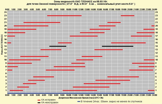
Rice. 1. Visibility zones of the GLONASS system for a given point on the earth’s surface
It is believed that for determination with the stated accuracy, the PDOP (positional three-dimensional geometric factor) value must be less than six. Integral availability is calculated based on the current almanac for a daily interval as the percentage of time during which this condition is met. In Fig. Figure 2 shows the integral accessibility of navigation for a ground user using the GLONASS system.
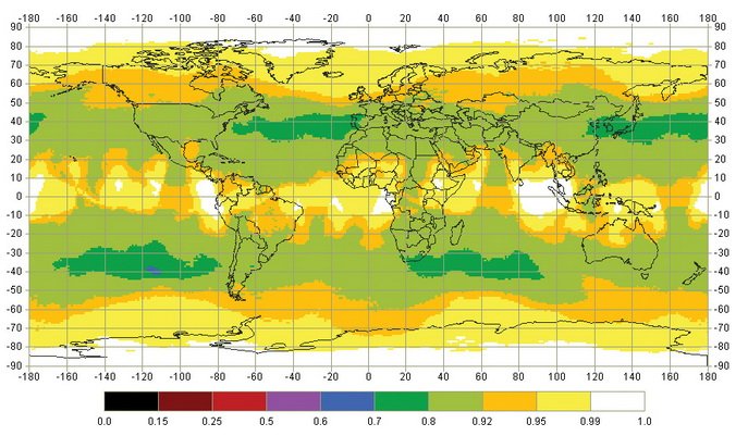
Rice. 2. Integral accessibility of navigation for ground users using the GLONASS system
Again, consider the expected commissioning of three recently launched satellites.
Attention of the Government of the Russian Federation to the GLONASS system
Let us recall that the satellite navigation system includes three segments:
- Space. This includes satellites launched into Earth orbit.
- Ground segment management. It consists of a main station combined with a computer center for a group of control and measuring stations, and a ground-based time and frequency standard. (For more details, see the sources).
- Ground segment of consumers. This includes the receiving equipment of all GNSS end users. The main task of consumer navigation equipment (CNA) is to receive information from satellites, interpret it and display it on a display or in a communication channel in the proper form.
If everything is clear with the first two segments (they are financed from the budget), then the third segment is paid for by the end user, and he must be convinced to switch from cheaper single-system GPS receivers to more expensive (and this is an objective reality) dual-system GLONASS/GPS.
The customers of the Ministry of Defense and other law enforcement agencies, as well as aviation, the navy and the Ministry of Emergency Situations do not need much convincing. It is clear there that since the NAVSTAR system belongs to the US Department of Defense, it is controlled by it, and, therefore, can be disabled (or roughened) in certain conflict situations or in other cases, if such a need arises (there were precedents). And there is nothing to object to here - this is their system. Another thing is that this decision will affect the interests of consumers, even if they are neutral in relation to this conflict situation. The presence of consumer equipment that supports its own navigation system would be an acceptable way out of the situation, albeit with some loss of quality. Similar departments of other states should show interest in dual-system equipment; the reason is also clear: there are two systems, even if both are foreign, but the probability that at least one will work is greater. However, the market size for military applications using navigation technologies is quite limited.
According to forecasts for 2010, more than 70% of the NAP market will be occupied by mobile devices (Cell Phones, PDA, navigators, etc.). In this market, there are few bright prospects for manufacturers of dual-system solutions. The end consumer, as a rule, is a private person who, for obvious reasons, is far from both security problems and benefits technical characteristics combined receivers. More low prices On the contrary, NAVSTAR receivers are close and understandable to private consumers. And it is unlikely that any government decisions will change this situation (especially since there are no mobile devices that support GLONASS yet).
The segment of corporate consumers remains. As a rule, this is equipment for monitoring vehicles. According to the same forecasts for 2010, its share in the NAP market will be 23%. The decline compared to 2000 is by no means due to a loss of interest in these applications - on the contrary, it is growing. But it is impossible to keep up with the rapid pace of implementation of navigation technologies in mobile devices. And in relation to the transport segment, the Government’s actions are quite adequate. The Decree of the Government of the Russian Federation of August 25, 2008 “On equipping transport, technical means and systems with GLONASS or GLONASS/GPS satellite navigation equipment” defines:
- The following vehicles, technical means and systems must be equipped with GLONASS or GLONASS/GPS satellite navigation equipment:
- space assets (launch rockets, upper stages, spacecraft and ships, descent capsules (devices));
- aircraft of state, civil and experimental aviation;
- sea vessels and vessels of inland river and mixed (“river-sea”) navigation;
- automobile and railway vehicles used for transporting passengers, special and dangerous goods;
- instruments and equipment used in carrying out geodetic and cadastral work;
- means for ensuring time synchronization.
Such a decision, of course, is protectionism, but it is quite understandable in relation to projects that, to one degree or another, are financed from the budget.
Another thing is that the further development of the ground-based user segment of GLONASS is impossible without investments in the development of the domestic element base for navigation equipment, as well as certain benefits for manufacturers of NAP hardware and software.
Advantages of navigation technology using the combined GLONASS/GPS constellation
Global navigation satellite systems determine location, speed and exact time. However, a significant factor influencing the accuracy of ground-based navigation equipment is the number of satellites visible in the sky. For guaranteed GPS operation an open space is required when the maximum number of satellites is in the field of view and there are no reflected signals.
In the presence of various obscurations of radio visibility, which are typical for the conditions of use in ground transport, and especially in the conditions of a modern urban landscape, the capabilities of accurate positioning are significantly deteriorated. The number of visible satellites of one system may be insufficient to solve the navigation problem with the required accuracy, and the solution itself often becomes impossible. The use of two navigation systems improves and expands the experience for consumers.
A typical example is the operation of a navigation receiver near the wall of a house, when physically half of the sky is closed. In such conditions, the use of GLONASS in conjunction with GPS significantly (almost twice) increases the reliability and reliability of the receiver in determining coordinates. Since solving navigation problems on ground transport involves working in conditions of partial and frequent obscuration of radio visibility, the GLONASS+GPS receiver has significant advantages over any single-system GPS or GLONASS receiver.
The GLONASS system, unlike GPS, allows reliable reception of a navigation signal in the northern and southern polar latitudes of the Earth.
Combined GLONASS/GPS receivers from GeoStar Navigation
Considering GLONASS/GPS receivers offered by domestic manufacturers, we will limit ourselves to only one class, namely OEM receivers, that is, complete modules intended for integration as an electronic component into finished products for various purposes. A number of manufacturers offer the market complete navigation products for marine, aviation, land carriers, and geodetic equipment, but these products are still based on OEM receivers.
KB GeoStar Navigation offers two receivers to the market: GeoS-1 and GeoS-1m. GeoS-1 is a complete board, shown in Fig. 3.
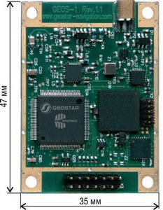
Rice. 3. Combined GLONASS/GPS receiver GeoS-1
The receiver uses signals from the satellites of both GeoS-1 navigation systems, which allows you to determine the exact location of an object where this is impossible (or possible with limitations - 2D mode) if the systems are used separately. The GeoS-1 receiver is capable of receiving location data using either only GLONASS signals, or only GPS, or working under the combined GLONASS+GPS constellation. Structural scheme receiver is shown in Fig. 4.

Rice. 4. Block diagram of the GeoS-1 receiver
The digital part of the GeoS-1 receiver consists of a LSI processor with ARM-7 architecture (AT91FR40162S from Atmel) and a correlator with an accelerator (automatic quick search), made on a custom-made LSI, which is a development of the Federal State Unitary Enterprise NIIMA “Progress”. The use of a specialized microcircuit ensures achievement of high time values from power supply to the first coordinates and high sensitivity of the receiver. Due to the hardware implementation of search algorithms, GeoS-1 provides navigation data within 36 seconds in a “cold” start and within 4 seconds in a “hot” start.
The accuracy of determining coordinates (standard deviation) in plan is 3 m, in height 5 m. The accuracy of determining speed is 0.05 m/s. The rate of delivery of navigation information is five times per second. The receiver outputs a time stamp pulse (1PPS - one pulse per second) with an accuracy of 50 ns in relation to the GPS-Time scale.
Receiver sensitivity in detection mode is -170 dBW; in tracking mode -180 dBW. Antenna requirements: active, with additional gain 10...35 dB.
Power 3.3V ±5%; power consumption in tracking mode is 500 mW, in standby mode (powered by a battery source) 20...30 μW.
Data exchange channels: one USB 2.0 channel, two duplex RS-232 channels (LVTTL signal levels) with a software-defined transmission speed of 4800...203400 bps. Depending on the exchange channels used (two RS-232 channels or one RS-232 + USB channel) and the design of the battery power supply (installed on the board or external), four design options are possible, designated in the order as the suffix “xx” in the name GeoS- 1xx. Overall dimensions of the product are 47x35x9 mm.
A photograph of the Geos-1m receiver is shown in Fig. 5.

Rice. 5. Combined GLONASS/GPS receiver GeoS-1m
Unlike GeoS-1, which is installed autonomously in user equipment and connected to user boards with cables, the GeoS-1m receiver is a surface-mounted module. The module is directly soldered onto the custom printed circuit board within a single installation cycle. Overall dimensions of GeoS-1m are 35x35x3 mm (that is, 47% smaller than GeoS-1). Execution option one - two RS-232 channels and an external battery source. Power consumption, compared to GeoS-1, is also reduced and amounts to 350 mW in tracking mode.
The technical characteristics of the module and its structure (except for the absence of a USB port) are similar to those given for GeoS-1.
Both receivers are civilian products. The high sensitivity of the receiver and the speed of determining coordinates, combined with small dimensions and low power consumption, ensure their successful use in on-board equipment various systems transport monitoring.
Protocols for issuing navigation information
Receivers provide two ways to exchange navigation information: the symbolic protocol NMEA 0183 v.3.01 and its own binary exchange protocol. Data in both protocols are issued by the receiver simultaneously, but each through its own channel. By default, channel No. 0 outputs binary protocol data, channel No. 1 - NMEA. Using the appropriate binary protocol command, it is possible to reassign information protocols to other communication channels, that is, the binary protocol will be issued on channel No. 1, and NMEA on channel No. 0. The USB channel can only transmit data from one of the protocols.
The NMEA protocol (National Marine Electronics Association) - full name “NMEA 0183” - is a symbolic protocol for communication between navigation equipment. It is used in almost all GPS receivers due to its simplicity. Since the receiver has a serial RS-232 interface, you can “communicate” with it by connecting it, for example, to an IBM PC-compatible computer (by agreeing, of course, on signal levels, transmission speed and sending format). Since the data format is character-based, the user can view and “decipher” messages (with some skill) using any terminal program (in the simplest case, the “HyperTerminal” program included in the Windows OS), without developing a special software.
The NMEA protocol does not provide for sending requests to the receiver. The receiver automatically generates a specific set of messages provided by the built-in software. GeoS-1 receiver packet format and their detailed description are given in the document “GeoS-1. Manual .
Own binary protocol. As a rule, the manufacturer of navigation receivers, in addition to the NMEA protocol, offers its own protocol that provides:
- Ability to configure receiver operating modes;
- Receiving expanded navigation (compared to NMEA) information;
- Receiving information in response to requests sent to the receiver.
The transmission format, as already noted, is binary (that is, binary) - the value of a specific parameter is transmitted not in ASCI codes, but in the form binary number; formats in terms of the C language (byte, short, int, float, double and others), selected depending on the bit depth and method of data presentation. Thus, viewing messages on a computer is possible, but the simplest terminal programs are unsuitable - for “decryption” it is necessary to use special programs.
Additional information may include almanac messages, ephemeris messages, measurement information from satellites, position data in both geographic (latitude, longitude, altitude) and geocentric (X, Y, Z distances from the geoid center) coordinates. Fine adjustments of the receiver are possible (for example, turning off and on a specific satellite based on the position) and other functions.
In general, the protocol contains a number of packets of unsolicited messages (that is, messages sent by the receiver automatically as they are formed), packets of settings, requests and commands received by the receiver from the controller and responses to settings, requests and commands that are sent by the receiver to the controller.
A complete list of binary protocol packages, their format and description are also given in.
Switching boards and GeoSDemo software
To demonstrate the operation of the receivers, switching boards have been developed (respectively, GeoS-1 DemoKit and GeoS-M DemoKit, shown in Figure 6) and software for personal computer GeoSDemo.

Rice. 6. GeoS-1 DemoKit and GeoS-M DemoKit switching boards
The switching board performs the following functions:
- Formation of a main supply voltage of 3.3V from an input DC voltage of 5...30V;
- Connecting an external backup voltage source (battery) to the receiver (for versions with external battery) and the ability to disable it (for using versions with a battery power supply installed on the board);
- Conversion of standard RS-232 signal levels to LVTTL levels and vice versa;
- Connection to USB ports and RS-232 personal computer;
- Switching the input supply voltage from external source or via USB connector;
- Buffering and output to the RF connector of the 1PPS second time stamp;
- Indication of the presence of 3.3V voltage and activity of the RS-232 ports.
The switching board connects the receiver to external equipment (power supply, USB/RS-232 ports of the computer).
GeoSDemo software is demo software for the GeoS-1 and GeoS-M receivers.
The program allows you to:
- Make an automatic or manual connection to the receiver via RS-232 and USB serial ports;
- Display output navigation information of the receiver, including in graphical form;
- Generate and send commands, requests and settings to the receiver;
- Display receiver responses to commands, requests and settings;
- Record output information in log files;
- Read previously recorded log files;
- Generate and record a protocol for the operation of the receiver;
- Update the receiver software;
Figure 7 shows the main window of the GeoSDemo program.
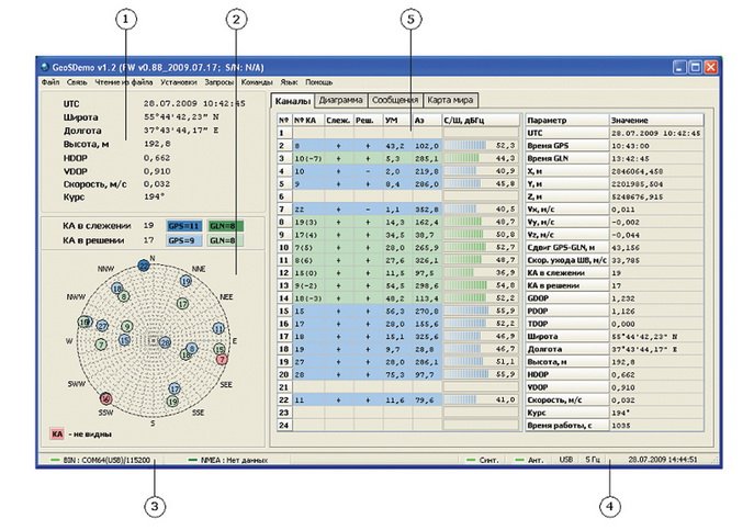
Rice. 7. Main window of the GeoSDemo program
Field 1 contains information about the date and time, geographical coordinates and height, values of the geometric factor DOP in the plane and in height, speed and heading of the carrier.
Field 2 contains a map of satellite positions, as well as information about GPS satellites and GLONASS, tracked by the receiver (“SC in tracking”) and taking part in the calculation (“SC in decision”). The map also displays satellites whose elevation angle is below the minimum.
In field 3 of the main window there is a status line, on the left side of which the connection status and parameters of the PC COM ports (number and baud rate) configured to receive binary and NMEA protocol data are displayed. The inscription “USB” to the right of the COM port number means that the connection is made through a virtual COM port, which is created by the USB driver.
Field 4 displays the computer's system date and time according to regional settings and the receiver's hardware telemetry status. Indicator "Syn." shows the telemetry status of the receiver's frequency synthesizer, and the "Ant." indicator - antenna supply voltage telemetry status.
In field 5 of the main window there is a panel containing a set of four tabs: “Channels”, “Diagram”, “Messages” and “World Map”.
More detailed information about the program, as well as procedures for saving and loading almanacs, ephemerides, setting and saving software settings in the receiver's Flash memory are given in the documents.
Conclusion
At this point in time, GLONASS is approaching a state that will allow it to be considered a full-fledged navigation system, capable of performing the declared functions even without the support of satellites of other navigation systems.
Of particular interest is the expected launch in 2010 of the third generation of Glonass-K satellites with a stated service life of 10 years. The appearance of third-band L3 signals will more than double the accuracy of location determination. And finally, the smaller mass of the satellite itself will make it possible to launch it from the Plesetsk cosmodrome (and not from Baikonur, as was previously the case) with a different upper stage and launch vehicle, which will reduce the cost of launching into orbit by approximately half.
Literature
- Soloviev Yu.A. Satellite navigation systems. - M.: Eco-Trends, 2000.
- Global satellite radio navigation system GLONASS. Ed. V.N. Kharisova, A.I. Perov, V.A. Boldin. - M.: IPRZHR, 1988.
- Yatsenkov V.S. Basics of satellite navigation. GPS systems NAVSTAR and GLONASS. - M.: Hotline- Telecom, 2005.
- Article “GLONASS Launches” on the website
http://ru.wikipedia.org/. - Samkova E. Review of the navigation devices market // Embedded systems, No. 3, 2009.
- Federal target program “Global Navigation System” dated August 20, 2001// Internet page
http://www.aggf.ru/proekt/zakon/doc.php?zakID=2. - Decree of the Government of the Russian Federation of August 25, 2008 “On equipping transport, technical means and systems with GLONASS or GLONASS/GPS satellite navigation equipment”// Internet page
http://www.aggf.ru/proekt/zakon/doc.php?zakID=6. - GeoS-1. Manual. Version 1.1. // document of the GeoStar Navigation company
http://www.geostar-navigation.com/fail/manuals/User_Manual_GeoS-1_rus.pdf. - GeoSDemo. User guide. Version 1.2. // document of the GeoStar Navigation company
http://www.geostar-navigation.com/fail/geosdemo/User_Manual_GeoSDemo_1_2_rus.pdf.